


General description
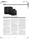
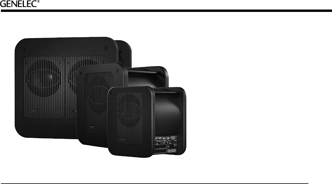
Genelec 7060A, 7070A and 7071A are pow-
erful active subwoofers, incorporating all the
amplifi er and crossover electronics needed
for bass management and reproduction in
modern 6.1 or 5.1 channel surround sound
or traditional stereo systems. Their 19 to 120
Hz (±3 dB) (29 to 120 Hz on the 7060A) fre-
quency range, ample sound pressure capa-
bility and versatile connections make these
subwoofers ideal companions for Genelec's
active monitoring speakers.
Bass management unit
The built-in bass management unit has six
signal input and output channels (L/C/R Front
and L/C/R Rear), a discrete LFE signal input
and a summed signal output, providing great
fl exibility and easy connection in all monitor-
ing environments.
The active crossover contained in the bass
management unit splits the input signals into
low and high frequency components at 85
Hz. Frequencies below 85 Hz are directed to
the subwoofer and frequencies above 85 Hz
to the main speakers.
The low pass section sensitivity can be
adjusted from +12 dBu to -6 dBu to allow
easy subwoofer level matching with various
main speakers. All outputs have 0 dB pass-
band gain.
The low pass frequency of the LFE input
channel can be set to 85 Hz, 120 Hz or 85 Hz
with "Redirect" function that routes LFE con-
tent above 85 Hz to the front center monitor.
The input sensitivity of the LFE channel can
be set to 0 dB or +10 dB.
Balanced XLR connectors are used for the
system audio inputs and outputs.
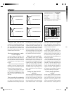
Two "Bass Roll-Off" switches are included
to provide a fl at bass response in all acous-
tical environments, enabling adjustments of
the subwoofer response in three -2 dB steps.
Two phase matching switches in the crosso-
ver allow compensation for the delay which
occurs if the subwoofer is placed away from
the main speakers, or for other speaker sys-
tems phase behaviour. Four settings are pro-
vided between 0° and -270°. An 85 Hz test
tone generator is included to help achieve
accurate crossover phase alignment.
Installation
Each subwoofer is supplied with a mains cable
and an operating manual. Once unpacked,
place the subwoofer in a suitable location (for
more details see the "Positioning" section).
Before connecting the audio signals, ensure
that both the subwoofer and the main moni-
tors are switched off. Check that the voltage
selector switch is set according to your local
mains voltage (subwoofers sold in Europe
have a fi xed 230V setting). Connections are
easier to make if you roll the subwoofer on
its side with the amplifi er panel facing up. Use
this position only for making the connections
and roll the subwoofer back to its normal
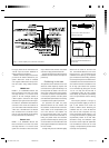
upright position before use. Audio connec-
tions to the subwoofer are made via balanced
XLR connectors. An unbalanced source can
also be used with a special RCA to XLR
cable; the correct connection for the cable is
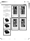
shown in Fig. 2. However, we recommend the
use of balanced cables and connectors due
to their better noise immunity. The connectors
are arranged in three rows on the amplifi er
panel (see Fig. 1):
Top row
LFE IN / SUM IN: Use this connector for
the LFE or .1 output channel of a 5.1- or
6.1-channel discrete surround sound source,
or the SUM OUT signal from the "master"
subwoofer in a daisy-chained multiple sub-
woofer confi guration. Note that the "sub-
woofer out" channel of an analogue matrix
surround decoder (Dolby Surround, Dolby
7060A, 7070A and 7071A Active Subwoofers
Gen 7060A+7070A+7071A 22.5.2002, 11:042
Prosessimusta