


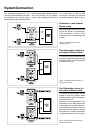
Coarse Phase Correction
Method
The method to coarse align the phase
of the system is as follows.
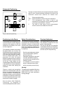
• Connect an audio frequency signal
generator to one of the channels used
in the system. If the signal generator
has an unbalanced output use a cable
with pin 3 grounded to pin 1 at the input
as shown in figure 4 below.
ON
1234
•Toggle the -180° phase
switch 'on' and 'off' and set it
to the position which gives
the lowest sound level at the
listening position.
ON
1234
• Finally, set the -180° phase
switch to the opposite setting.
Connect a high grade measuring
microphone to the analyser and feed
pink noise into the left main monitor.
Position the microphone at the listening
position and adjust the input sensitivity
of the subwoofer until frequencies
below and above 85 Hz are reproduced
with equal level. Then adjust the phase
control switches until a clear dip of at
least -6dB can be seen at the crossover
frequency (85 Hz).
If a dip appears at several switch
positions select the one that gives the
deepest reading. This should be the
case where the phase difference
between the subwoofer and the main
monitors is at a maximum. To change
the phase difference to a minimum the
-180° switch should be moved to the
opposite setting. The frequency
analyser should now show the
smoothest response around 85 Hz
and the phase should now be set
correctly. Repeat the above procedure
with the right channel and possible
centre channel main monitors.
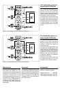
ON
1234
• Next toggle the -90° phase
switch 'on' and 'off', and again
set it to the position which
gives the lowest sound level.
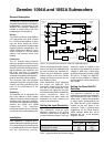
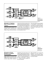
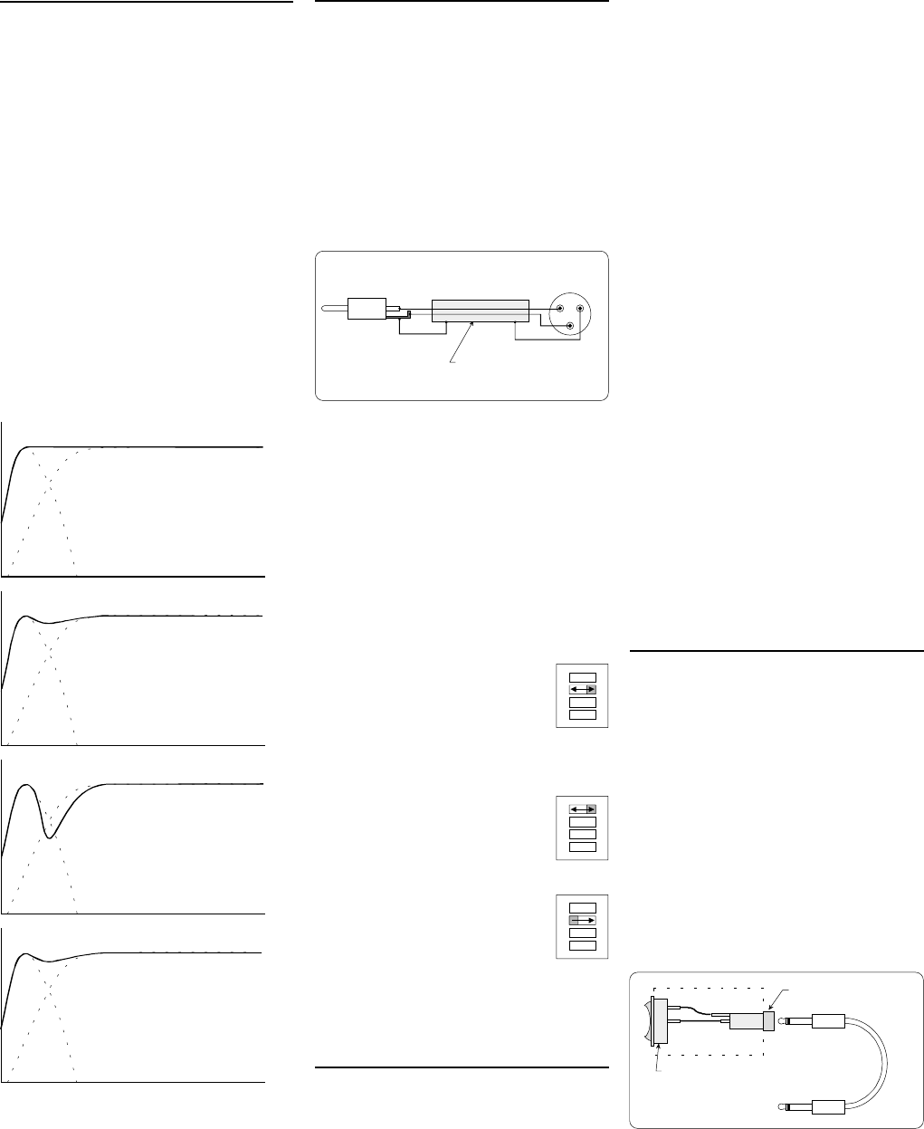
Phase Difference: 0°
Phase Difference: 90°
Phase Difference: 180°
Phase Difference: 270°
85 Hz
85 Hz
85 Hz
85 Hz
Setting the Phase Control
The effect of incorrect phase alignment
between main monitors and subwoofer
is a drop in the frequency response of
the whole system at the crossover
frequency. The graphs below (figure
3) show the effect of phase difference
on the frequency response.
The phase difference between the
main monitors and subwoofer at the
listening position is dependent upon
the position of the subwoofer in the
listening room. For accurate system
alignment in the room acoustic
measuring equipment is required. If
this equipment is not available to the
user coarse phase matching can be
applied.
Figure 4. XLR to RCA connector for
unbalanced operation.
21
3
SCREEN
CABLE
RCA
XLR
MALE
• Set the frequency generator to 85Hz.
If a signal generator is not available
then it is possible to use an audio test
recording with a test frequency in the
range 70Hz to 100Hz.
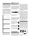
Subwoofer Bypass Control
A bypass control feature is included
into the subwoofer circuits so that the
effect of the subwoofer on the whole
monitor system can be determined.
With the bypass switch on, the high
pass filters for the main monitors are
bypassed and the system behaves as
if the subwoofer were not connected.
The bypass remote controller is
inserted into the ¼ inch jack socket
located on the rear amplifier panel.
See figure 5 for construction details.
SPST Switch
Mono ¼inch
Jack Socket
Figure 5. Bypass Remote Switch
Construction.
Phase Correction Method
with Test Equipment
If a frequency analyser and a pink
noise generator are available then the
following procedure can be used to
match the phasing between the
subwoofer and the main monitors.
Figure 3. The effect of phase difference
between the subwoofer and the main
monitors