


Page 4
Introduction
Congratulations on purchasing a Gemini SA-600 turntable. This state of the
art turntable includes the latest features. Prior to use, we suggest that you
carefully read all the instructions.
Features
• ±10% Pitch control
• Braking for quick stops
• Strobe illuminator
• Soft-touch start/stop switch
Precautions
1. Read all operating instructions before using this equipment.
2. The apparatus should not be exposed to dripping or splashing and no
objects filled with liquids such as vases should be placed on the
apparatus.
3. To reduce the risk of electrical shock, do not open the unit. There are
NO USER REPLACEABLE PARTS INSIDE. Please contact the Gemini
Service Department or your authorized dealer to speak to a qualified
service technician.
In the U.S.A., if you have any problems with this unit, call
1-732-969-9000 for customer service. Do not return
equipment to your dealer.
4. Tone arm bearings are factory set and sealed. Any attempt at adjust-
ment will void the warranty.
5. Be sure that all AC power is OFF while making connections.
6. Cables should be low capacitance, shielded and of proper length. Make
sure that all plugs and jacks are tight and properly connected.
7. Always begin with the audio level faders/volume controls set at
minimum and the speaker volume control(s) set to OFF. Wait 8 to 10
seconds prior to turning up the speaker volume to prevent the transient
“POP” that could result in speaker/crossover damage.
8. DO NOT EXPOSE THIS UNIT TO RAIN OR MOISTURE.
9. DO NOT USE ANY SPRAY CLEANER OR LUBRICANT ON ANY
CONTROLS OR SWITCHES.
Parts Checklist
Turntable unit.............................................................................1
Dust cover hinge...........................................................................2
Turntable platter.............................................................................1
45 RPM adapter..................................................................................1
Rubber mat......................................................................................1
Counter balance..............................................................................1
Dust cover..........................................................................................1
Headshell..........................................................................................1
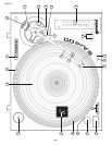
Assembly and Set-Up
SEE FIG. 1 ( PAGE 1 ) FOR PART NUMBERS AND LOCATIONS.
TURNTABLE INSTALLATION:
1. Set the TURNTABLE BASE (1) on a flat, level surface free of vibration.
Try to place the unit as far away from the speakers as possible. Keep
the unit away from direct exposure to the sun, heat, moisture or dirt.
Keep the unit well ventilated. Use the turntable feet to horizontally
stabilize the unit.
2. Make sure that the VOLTAGE SELECTOR (3) switch (located on the
TURNTABLE BASE) is set to the correct voltage. WARNING: If you try
to operate the turntable with the incorrect voltage setting, it can damage
your turntable.
3. After checking to ensure that all packing materials have been removed,
gently place the PLATTER (2) on the center spindle of the TURNTABLE
BASE (1).
4. Put the RUBBER MAT (4) on the PLATTER (2).
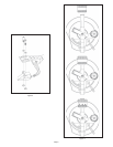
CARTRIDGE INSTALLATION: (SEE FIG. 2)
Because all cartridges have their own designs, please refer to your
particular cartridge’s instructions to insure proper installation.
1. Connect the lead wires to the cartridge terminals. For your convenience,
the terminals of most cartridges are color coded. Connect each lead
wire to the terminal of the same color.
White (L+).................................Left Channel +
Blue (L-)....................................Left Channel -
Red (R+)................................Right Channel +
Green (R-).............................Right Channel -
2. Mount the cartridge in the HEADSHELL (5) and tighten it with the
screws included with the cartridge.
HEADSHELL INSTALLATION:
Insert the HEADSHELL (5) into the front of the tubular TONE ARM (6).
While holding the HEADSHELL (5) firmly in a horizontal position, turn the
LOCKING NUT (7) counter clockwise until the HEADSHELL (5) is locked in
place. The Gemini angled headshell was designed to be used with a
straight tone arm. Any type of cartridge can be mounted in the Gemini
angled headshell.
USING A STRAIGHT TONE ARM:
When using a straight tone arm with a banana stylus or a cartridge
mounted in a standard headshell, you should always use a conical type of
needle. If you use an elliptical needle, the needle will sit in the groove of the
record properly, but one channel will be louder than the other channel.
The Gemini straight tone arm has been designed so that it will line up with
markings on LPs you have made when using a turntable with an S-shaped
tone arm.
COUNTERWEIGHT INSTALLATION: (SEE FIG. 3)
1. Slide the COUNTERWEIGHT (8) onto the rear of the TONE ARM (6)
with the numbered stylus gauge facing forward.
2. Twist the COUNTERWEIGHT (8) lightly counter clockwise, to screw it
onto the rear of the TONE ARM (6).
ADJUSTING HORIZONTAL ZERO (0) BALANCE AND
STYLUS PRESSURE:
1. Without touching the stylus tip, remove the stylus protector (if your
cartridge has a detachable one).
2. Release the ARM CLAMP (9) and lift the TONE ARM (6) off the ARM
REST (10).
3. Counter clockwise advancement of the COUNTERWEIGHT (8) will
cause the cartridge side of the TONE ARM (6) to be lowered. Clockwise
will cause the opposite. Turn the COUNTERWEIGHT clockwise or
counter clockwise as needed until the TONE ARM is balanced horizon-
tally. You can easily tell this by watching for the point where the TONE
ARM “floats” freely.
4. Place TONE ARM (6) on ARM REST (10) and lock it in place with the
ARM CLAMP (9).
5. With the TONE ARM (6) locked on the ARM REST (10), hold the
COUNTERWEIGHT (8) steady with one hand while rotating the
STYLUS PRESSURE RING (11) until the numeral “0” on the ring aligns
with the center line on the TONE ARM (6) rear shaft. The horizontal
zero (0) balance should be completed.
6. Refloat the TONE ARM to ensure horizontal zero (0) balance. If zero
balance has not been maintained, repeat counterweight steps 3 - 5.
7. After adjusting the horizontal zero (0) balance, turn the balanced
COUNTERWEIGHT (8) counter clockwise until the cartridge
manufacturer’s recommend stylus pressure appears on the STYLUS
PRESSURE RING (11) where it meets the center line of the TONE ARM
(6) rear shaft.