Electro-Voice® EVA Series User Manual
5.0 EVA Rigging System (cont’)
While 80-90% of EVA applications will be accommodated with arrays of three or four modules. Up to
eight EVA modules may be suspended together up to a combined maximum loudspeaker column weight
of 720 lbs.
5.2 Deciding Which Grid Configuration to Use with an EVA Array
5.21 Standard Grid with or without Second Spreader Bar
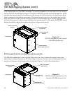
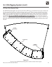
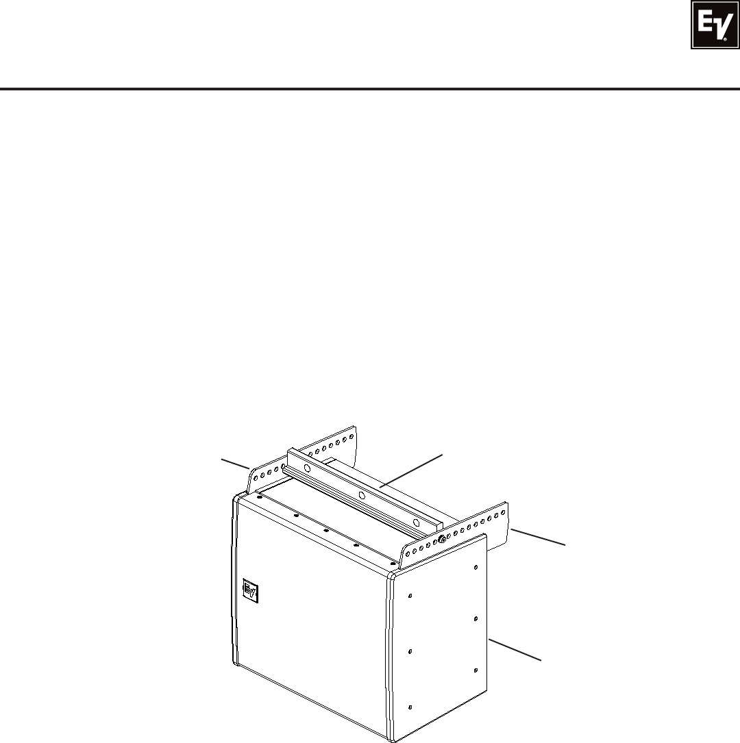
The EVA-SG standard grid is shown in Figure 15. This grid is appropriate for those 80-to-90% of appli-
cations covered by a three- to four-module array. It comes with one spreader bar and two side arms, plus
the two shoulder bolts and nylon washers required to assemble the three parts into a grid. The spreader
bar has three 0.813-inch (20.6 mm) holes through it, one near each end and one in the center, to which
the chain hoist(s) or other device(s) used to lift the array into position can be attached. Using the two end
points provides horizontal stability for the array. Using the center point will probably require a tie-off to
stabilize the horizontal position of the array.
Figure 15:
EVA-SG grid (down angle of the array is determined by
the front-to-back position of the spreader bar)
When the standard grid with its single spreader bar is used, the down angle of the array is determined by
the front-to-back attachment position of the spreader bar. This information is provided by Electro-Voice’s
EVA Design Assistant (EVADA™), a function of the array makeup and desired vertical aiming. See section
3.0 Designing an EVA Array, above.
For arrays (1) larger than four EVA modules or (2) three- to-four-box arrays with extreme down angles, the
extended grid is usually required. See section 5.22 Extended Grid with or without Second Spreader Bar,
below.
Standard (EVA-SG)
Sidearm
Spreader Bar
EVA Module(s)
(Not Included with Grid)
Standard (EVA-SG)
Sidearm
21


