


SP-20AB MANUAL
contact between chassis, as in a rack with
metal rails. Sliding the Ground Lift switch up
completely isolates all signal grounds from
the chassis, breaking any ground loops. The
chassis always remains con nected to the
ground pin on the AC cord for safety and to
provide shielding against RF interference.
Try both positions of the Ground Lift switch,
and leave the switch in the position that
results in the least hum in your system. Note:
The ground lift can be rendered ineffective by
3 pin audio connectors that tie pin I (signal
ground) to the metal shell of the connector
(chassis ground). The connection from pin 1
to the shell is optional on all 3 pin connec-
tors, and can be removed if present, by
opening up the connector on the cable and
disconnecting it.
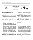
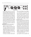
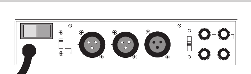
MODE SWITCH:
This three position slide
switch determines the SP-20AB’s mode of
operation The three choices are:
MONO:
This position is also referred to as
“Dual Mono” because while both channels
are operating separately (each driving its
own speaker), there is only one input, which
appears at both outputs. The input must be
connected to the “Left/Mono Input” jack.
STEREO:
This position is for normal stereo
operation, where there are two inputs (left
and right) and two outputs.
BRIDGED:
This position should be used
for straight mono operation, when there is
only one input (plugged into the “Left/Mono
Input” jack) and all the SP-20AB’s power is
to be concentrated into one output. Note
that under some circumstances, this can
amount to more than double the rated 20
watts pet channel for stereo .- to as much
as 50 watts. Therefore, in bridged mode, for
adequate
protection, the speaker connected
should be able to handle approx imately 100
watts without damage. See “SPEAKER
OUTPUTS” below for de tails of how to
connect the speaker.
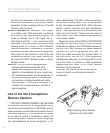
SPEAKER OUTPUTS:
These outputs should be
used for driving speakers. The connections
are via multiple-use terminals, which can
accommodate either dual banana plugs,
bare wires, or wires terminated in spade lugs.
For stereo or dual mono operation, connect
one speaker to the left pair of terminals and
the other speaker to the right pair. Observe
proper polarity - make sure that the wire
connected to the top (red) terminal on the
left channel connects to the red terminal of
the left speaker, and that the wire connected
to the top (red) terminal on the right channel
connects to the red terminal of the right
speaker. If the wires to one speaker are
reversed, the speakers will be of op posite
polarity (or “out of phase”), and a severe loss
of low frequencies may, result.
If Mono Bridged operation is desired, the
single
speaker must be connected to the
4
1
2
3
4 6
8
9
10
0
5
7
INPUT LEVEL
LEFT
20 WATTS / CHANNEL
RIGH
T
OVERLOAD
SPEAKER
S
SIGNAL
MONO
STEREO
L
BRIDGED
R
USE FOR BRIDGED
MODEL SP-20A
SATELLITE / REMOTE
VOLUME
LEFT / MONO INPUT
SPEAKERS
ON
RIGHT INPUT
OFF
1
2
3
4 6
8
9
10
0
5
7
120 VAC
60 Hz
130 Watts
HEAD
PWR
ON
STEREO AMPLIFIER
PHONE
OFF
LIFT
GND
LEFT RIGHT
SPEAKERS
MONO
STEREO
BRIDGED
USE FOR BRIDGED
SATELLITE / REMOTE
LEFT / MONO INPUT
RIGHT INPUT
120 VAC
60 Hz
130 Watts
ON OFF
LIFT
GND