


7
H A - 6 A B / H A - 6 A B E M a n u a l
sis ground). The connection from pin 1 to the shell
is optional on all 3 pin connectors, and can be
removed if present, by opening up the connector
on the cable and disconnecting it.
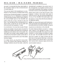
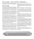
SPEAKER A OUTPUTS: These outputs should
be used when a pair of speakers is used as an
alternative to headphones, since the headphones
are switched off when the speakers are switched
on. The connections are 5-way binding posts,
which can accommodate dual banana plugs, bare
wires, or wires terminated in spade lugs.
SPEAKER B SATELLITE/REMOTE OUTPUT:
This output is a single male XLR connector con-
taining both the left and right channel outputs. It
is wired as follows: Pin 3-left (high); Pin 2-right
(high); and Pin 1-low, common to both channels.
This output should be used as the starting point
for a chain of HR-2 Remote Stations (satellites).
It will receive signal whenever the front panel
SPEAKER B button is depressed. If necessary,
it may also be used to connect a second set of
speakers. However, if it is used for speakers, note
that depressing the SPEAKER B button will not
switch off the front panel headphone jacks in the
way that the SPEAKER A button does.
INPUTS: Quarter-inch (mono) phone jacks are in-
tended for line level signals such as the outputs of
a mixer. Microphones and/or instrument pickups
may not have strong enough outputs to drive the
REAR PANEL
ON-OFF SWITCH: This switch turns the HA-6AB
on and off. For convenience, it is recommended
that the HA-6AB and any other rack-mount
equipment be powered through a switchable
outlet box, such as the Furman Sound PL-8 or
PL-PLUS Power Conditioner and Light Module.
The PL Series provides an easy way to power up
the whole rack with one front-panel switch, and
provides discreet illumination on dark stages and
studios as well. If you do use a switchable outlet
box, leave the HA-6AB’s on-off switch in the ON
position at all times.
GROUND LIFT SWITCH: In many installations,
hum-causing ground loops are formed by the
common connection of various pieces of equip-
ment to the power line ground, and by contact
between chassis, as in a rack with metal rails.
Sliding the Ground Lift switch up completely
isolates all signal grounds from the chassis,
breaking any ground loops. The chassis always
remains connected to the ground pin on the AC
cord for safety and to provide shielding against RF
interference. Try both positions of the Ground Lift
switch, and leave the switch in the position that
results in the least hum in your system.
Note: The ground lift can be rendered ineffective
by 3 pin audio connectors that tie pin 1 (signal
ground) to the metal shell of the connector (chas-
120 VAC
50/60 H
z
130 Watts
LIFT
GROUND
OFF
ON
SATELLITE / REMOTE
BALANCED INPUT
LEFT INPUT
HEADPHONE/
MONITOR
AMPLIFIER
BALANCED INPUT
RIGHT INPUT
SPEAKER B
SPEAKER A
RIGHTLEFT
AVIS:
RISQUE DE CHOC
ELECTRIQUE -- NE PAS OUVRIR
RISK OF ELECTRIC SHOCK. DO NOT OPEN.
REFER SERVICING TO QUALIFIED SERVICE
PERSONNEL. TO REDUCE THE RISK OF FIRE
OR ELECTRIC SHOCK DO NOT EXPOSE THIS
EQUIPMENT TO RAIN AND MOISTURE.
CAUTION!
LISTED
7Z37
PROFESSIONAL
AUDIO EQUIPMENT
® ®