


FLYING MOLE CORPORATION
5199-1 Waji-cho, Hamamatsu 431-1115 Japan.
Tel : +81-53-486-6030 Fax : +81-53-486-6033
http://www.flyingmole.co.jp
This document is printed with soy ink
(an organic ink made from soy oil) on
recycled paper. Environmentally
friendly printed matter.
FP40697-000
Privacy Policy
Security of Collected Information
We maintains strict physical, electronic, and administrative safeguards to protect
your personal information from unauthorized or inappropriat e access. We
restricts access to information about you to who need to know the information to
respond to your inquiry or request. Who misuse personal information are subject
to disciplinary action.
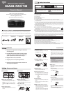
Maintenance
Never use liquids such as benzine, thinners,
etc., chemically treated cloths, and do not spray
any aerosol type insecticides on the amplifier.
Clean the case using only a soft, dry cloth.
If the amplifier becomes soiled, mix a solution
of water and a neutral detergent then dampen
a soft cloth in the solution, wring out as much
of the solution as possible, and clean the am-
plifier. Then use a soft, dry cloth to wipe the
surface dry.
Soft cloth
Neutral
detergent
Benzine
Liquids
7
Dimensions
6
370 (14-9/16”)
24
(15/16”)
11
(7/8”)
405 (15-15/16”)
210 (8-1/4”)
2
(1/16”)
2
(1/16”)
214 (8-7/16”)
88
(3-7/16”)
3
(1/8”)
91
(3-9/16”)
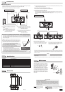
Connections
4
■ Connecting Devices
●
Make sure the power of all related equipments is turned off, when wiring and checking their polarity.
●
Make sure that the cable is not shorted, when connecting the speaker cable.
●
Connect the power cable after all connections are complete.
Unit: mm (”)
●
This product should be placed close to the main source of electrical power (wall outlet in your house)
and keep the power plug within reach.
●
Connectors names may be different from this manual.
✱ Refer to the owner’ s manuals of the equipments to be connected as well.
Power Amplifier, etc.Preamplifier, CD Player, etc.
Speaker
Connect to AC Outle
t
AC Power Cable
(*3)
(*1, 2)
(*1)
Preamplifier, CD Player, etc.
(* 4)BALANCE SIGNAL PARALLEL CONNECTION
Outputs from a preamplifier or a CD player can be input to more than one power amplifiers by connecting as shown below.
Power can be interlocked by using REMOTE POWER CONTROL trigger connectors.
(Refer to the “u Connection of the REMOTE POWER CONTROL Trigger” section for information about REMOTE POWER
CONTROL.)
(* 1) Select an input with the selector on the rear panel of the
amplifier.
• FIXED (The LEVEL adjustment knob on the front panel
is bypassed.)
• VARIABLE ( The level can be adjusted with the LEVEL
adjustment knob on the front panel.)
• BAL (The level can be adjusted with the LEVEL ad-
justment knob on the front panel.)
(* 2) XLR cables can be used to connect BALANCE outputs
of a CD player, preamplifier, etc. The signal arrangement
of the BALANCE INPUT on this product is:
1: GND, 2: HOT, and 3: COLD
(* 3) When balance signals are input, the same signals as the
input signals are output. The signal arrangement of the
BALANCE OUTPUT on this product is:
1: GND, 2: HOT, and 3: COLD
● Connection of the REMOTE POWER CONTROL Trigger
By connecting the REMOTE POWER CONTROL Trigger, the activation/deactivation of power on a Flying Mole
power amplifier equipped with REMOTE POWER CONTROL Trigger Input can be interlocked with the activa-
tion/deactivation of power on this device. Refer to the owner’s manuals of the devices to be connected as well
before connecting cables.
1. Remove the attachment to the REMOTE POWER CONTROL connec-
tors.
2. Remove insulation material around the ends of the supplied remote con-
nection cables and twist the wires until they are stranded securely.
3. Insert the wires into the holes in the attachment and tighten the screws
to fix the cables.
(Be sure to check polarity before connection)
* Connect the other ends of the cables to the connector for the device whose
power is to be interlocked as in the steps 1 to 3 above.
(The connector is also attached to the device to be connected.)
4. Connect the connectors to the REMOTE POWER CONTROL connec-
tors of the amplifier and of the other product.
•To control the power of the amplifier from the other product, connect the con-
nectors to the "IN" of this product and to the "OUT" of the other product.
•To control the power of the other product from this product, connect the con-
nectors to the "OUT" of the amplifier and to the "IN" of the other product.
* Commercially available vinyl insulated cables can be used as well. • Compatible cable type is AWG24 to AWG12.
Refer to the steps 1 through 4 above when connecting cables and make sure that the polarity is correct.
Remote connection
cable
+
–
* Be sure to check polarity before
connection.
Connect the black cable to the
negative terminal.
Specifications
5
Rated Output 300W / 4Ω, 100W / 8Ω
Total Harmonic Distortion 0.05% (@90W/8Ω / 1kHz)
Frequency Response DC–20kHz (+0dB / –0.5dB) / 8Ω DC–50kHz (+0dB / –3dB) / 8Ω
S/N Ratio 120dB (IHF-A, INput short-circuited)
Input Sensitivity UNBAL : 1V / BAL : 2V
Input Impedance FIXED : 100kΩ, VARIABLE : 47kΩ (BAL / UNBAL, Vol MAX)
Power Consumption 55W
Power Supply AC 120V 60Hz (U.S.A.) / AC 230V 50Hz
Use Environment 0°C – 40°C
Dimensions inch / mm 8-7/16" (W) x 3-9/16" (H) x 15-15/16" (D) / 214 (W) x 91 (H) x 405 (D)
Weight 4.0 kg (8.8 lbs)
* Nameplate is on the bottom of the product.
* Due to product improvement, specifications and/or product design are subject to change without notice.
● Connecting a Speaker Cable
q Strip the cover of the cable by about 10mm (3/8”).
w Twist the wires until they are stranded securely.
10mm
e Tu rn a speaker connector counterclockwise to loosen it.
r Insert the whole stranded wires of the cable and turn the
speaker connector clockwise to tighten it.
*Twist the wires of the speaker cable until they are stranded securely and take care not to leave any part of the stranded wires out
of the speaker connector when connecting the speaker cable. If the wires come in contact with the rear panel or the wires at the
positive terminal come in contact with the wires at the negative terminal, the protection circuit may be activated to stop the normal
operation of the product.
Caution
●
This product has DC amplifier circuit construction. (Sound signal goes through no capacitor from input to the
speaker output.)
Therefore, a little noise may be heard when the power is turned on or off depending on the connected device.