Operation
Installation
3
3-1
Section 3
Operation
3.1 Installation
Installation consists of mounting the equipment, making the required electrical connections, and entering
the desired set points.
CAUTION
Remove all power prior to installing the
Preamplifier.
Preamplifier Mounting
The preamplifier is a self-contained unit that is designed for mounting on a wall, or structurally sound
surface, within 6 feet of the detector. The preamplifier must be located in an area that is accessible for
future maintenance.
CAUTION
Remove all power prior to connecting field wiring.
Electrical Interface
Electrical connections at the preamplifier include connecting the detector high voltage and signal coaxial
cables and the field cable from the associated controller.
The detector high voltage and signal cables enter the preamplifier through “Seal Grip” type penetrations
on the enclosure body. The “Seal Grips” contain a rubber gland that is intended to grip the coaxial cables
to prevent moisture entry into the enclosure. The “Seal Grips” are an integral part of the detector cables.
The “Seal Grip” enclosure nut is removed from the fitting. The insulating washer stay with the fitting. The
detector signal and high voltage cables, with connectors and “Seal Grip” fitting nuts are then inserted into
the holes preamplifier enclosure. The “Seal Grip: end fittings are then re-installed securely against the
wall of the enclosure.
The detector Signal (BNC) and High Voltage (SHV) cables are then terminated on the bulkhead
connectors located on the enclosure inner panel.
On the 943-227-15 or 943-227-15VL, the field cable is terminated on a “MS” type connector. A mating
“MS” style connector supplied with the detector. It is not necessary to open the preamplifier enclosure to
complete the interconnection to the associated controller.
On the 943-227-15VL-M1, a 2.0-inch conduit hub is provided to interface with the field conduit system
and cable. The field conduit is connected to the preamplifier conduit hub and the field cable is routed
through the conduit and into the preamplifier enclosure. The field signal cable is then terminated on the
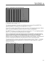
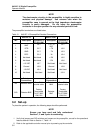
terminal block in the enclosure. Refer to the applicable wiring diagram or Table 3-1. The high voltage
coax cable is then terminated on the mating SHV connector. Refer to Appendix D for further information.
A desiccant bag is provided in the enclosure to absorb moisture. The desiccant bags should be checked
for moisture absorption prior to placing into service. Each bag contains a color indicator stripe that turns
red when it should be replaced.


