Appendix
Cable Termination Instructions
D
D-1
Appendix D
Cable Termination Instructions
D.1 Cable Termination Instructions
The procedures and instructions provided in Appendix D are provided for reference in terminating the field
cables to the Digital Preamplifier. A mating SHV connector is provided with the preamplifier. Ring lug
terminals are to be provided by the user. The instructions provided below are based on the use of P/N
50-100 multi-conductor cable. For other customer-supplied cables, the same basic procedures, modified
for the specific cable used, may be utilized.
Detector Cable Termination:
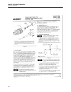
The detector high voltage and signal cables enter the preamplifier through “Seal Grip” type penetrations
on the enclosure body. The “Seal Grips” contain a rubber gland that is intended to grip the coaxial cables
to prevent moisture entry into the enclosure. The “Seal Grips” are an integral part of the detector cables.
The “Seal Grip” enclosure nut is removed from the fitting. The insulating washer stays with the fitting.
The detector signal and high voltage cables, with connectors and “Seal Grip” fitting nuts are then inserted
into the holes preamplifier enclosure. The “Seal Grip: end fittings are then re-installed securely against
the wall of the enclosure.
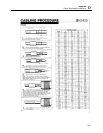
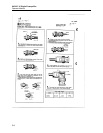
Detector Field Cable Preparation, “MS” Connector:
Prior to stripping the outer cable jacket, a 4-inch length of 0.75 I.D. shrinkable tubing (provided by the
user) should be slid over the 0.675 in cable jacket. The shrink tubing will be used to seal and protect the
end of the cable after the termination process is completed. To prepare the cable for termination, a
minimum of 7 inches of the cable outer jacket must be stripped off the cable. This will allow for the
stripping of approximately one inch from the various conductors, and provide 6 inches of actual service
loop cable. In addition, for EMI/RFI protection, the drain wire must be terminated to an earth ground
within the enclosure. The length of the drain wire will be based on the distance between the cable entry
and the ground location. The length of cable jacket to be stripped will then be based on the distance to
the drain wire grounding point.
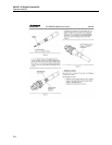
Once the cable outer jacket is stripped to the proper length, the aluminum tape shield and Mylar binder
may be removed, taking care not to damage the No. 20 AWG drain wire. The drain wire may then be
separated from the remaining conductors, for routing and termination at the grounding point.
Next, the HV coaxial cable may be separated from the bundle, followed by the single conductors wires
that are required for the specific application, and the polyester filler cord. Refer to the project specific
detector loop drawing, or the generic detector loop drawing provided in Appendix B for actual conductors
to be used.
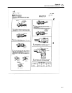
The polyester filler cord may now be removed. Cut the cord as close to the outer jacket as possible.
The single conductors may now be stripped and soldered to the appropriate connector pin.


