


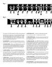
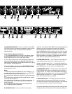

Twin Front Panel Functions (Fig.1)
A. INPUT 1 — A high impedance, high sensitivity plug-in connection
for instruments.
B. INPUT 2 — A plug-in connection for instruments. This input
exhibits less input impedance and sensitivity than INPUT 1, making it
useful for guitars that have active pickups. This input will provide a
darker tone if used with guitars that have passive pickups.
Note: INPUT 1 and INPUT 2 are inputs for both Channel One and
Channel Two.
C. VOLUME — Adjusts the overall volume of the Channel One Clean
Sound.
D. PULL BRIGHT — This pull switch on the Clean Sound VOLUME
control (item C) boosts the highs. This has the sonic effect of adding
high end “sparkle” (to the Clean Sound only).
E. GAIN — Adjusts the gain for the Channel One Vintage Drive
Sound. Lower settings provide an “on-the-edge” clean sound, while
higher settings provide gradual compression, like a “cranked” vin-
tage amp, but at controllable volumes. This control works in con-
junction with the Channel One Vintage Drive Sound VOLUME control
(item J) to set the overall volume of the Channel One Vintage Drive
Sound.
F. TREBLE — Adjusts the amount of boost or cut in the high frequency
range of Channel One.
G. BASS — Adjusts the amount of boost or cut in the low frequency
range of Channel One.
F. MID — Adjusts the amount of boost or cut in the middle frequency
range of Channel One.
I. VINTAGE DRIVE INDICATOR — When lit, this yellow LED indicates
that the Channel One Vintage Drive Sound is selected, and that the
Channel One Vintage Drive Sound GAIN (item E) and VOLUME
(item J) controls are active.
J. VOLUME — Adjusts the overall volume of the Channel One
Vintage Drive Sound.
K. PULL GAIN SELECT — When this pull switch on the Vintage Drive
Sound VOLUME control (item J) is in the “in” position, the Channel
One Clean Sound is selected and the Clean Sound VOLUME control
(item C) is active; when in the “out” position, the Vintage Drive
Sound is selected, and the Channel One Vintage Drive Sound GAIN
(item E) and VOLUME (item J) controls are active. This pull switch is
overridden when the footswitch is connected.
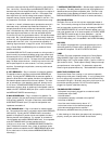
L. GAIN — Adjusts the amount of gain in Channel Two. Lower set-
tings provide gradual compression, while higher settings provide
more sustain... lots more sustain.
M. TREBLE — Adjusts the amount of boost or cut in the high frequen-
cy range of Channel Two.
N. BASS — Adjusts the amount of boost or cut in the low frequency
range of Channel Two.
O. MID — Adjusts the amount of boost or cut in the middle frequen-
cy range of Channel Two.
P. CHANNEL TWO INDICATOR — When this red LED is lit, Channel
Two is selected, and the Channel Two GAIN (item L) and VOLUME
(item Q) controls are active.
Q. VOLUME — Adjusts the overall volume of Channel Two. As this
control is rotated clockwise from the “1” position, the volume comes
up slowly at first for additional control at lower listening levels; but
near mid volume settings, the volume comes up faster for perfomance
levels.
R. PULL CHANNEL SELECT — When this pull switch on the Channel
Two VOLUME control (item Q) is in the “in” position, Channel One is
selected. When it is in the “out” position, Channel Two is selected.
This pull switch is overridden when the footswitch is connected.
S. MIX — Adjusts the amount of audible “wet” (processed) signal
when the variable level effects loop (located on the back panel) is
used. When the MIX control is in the full counter-clockwise position
(“1”), the “wet” signal will not be audible. When the MIX control is
in the full clockwise position (“10”), only the “wet” signal will be
heard (depending on the type of effect used). When nothing is
plugged into the EFFECTS RETURN jack (located on the rear panel),
the MIX control will have no effect on the sound. Also see the
“EFFECTS SELECT” switch in the Twin Rear Panel Functions section of
this manual.
T. REVERB — Adjusts the amount of reverb present in Channel One
and Channel Two. When the footswitch is connected, the reverb can
be turned on and off remotely. Also see the “REVERB SELECT
SWITCH” in the “Twin Amp Rear Panel Functions” section of this
manual.
U. PRESENCE — This is a true vintage-style PRESENCE control that
affects the way the power amplifier responds to upper high frequen-
cies. As the control is turned clockwise, the power amplifier (in inter-
action with the speaker load) enhances upper highs, giving the
Twin’s overall sound a “sparkling” quality.
V. PILOT LAMP — When this lamp is illuminated, the amplifier is
receiving power. Should the lamp burn out, turn off the amplifier and
unplug it from its power source, unscrew the red jewel, and replace
the lamp with type T47 light bulb.
Twin Rear Panel Functions (Fig. 2)
A. FUSE — The fuse is in the AC supply of the amplifier and will pro-
tect the amplifier and the operator in the event of an electrical fault.