


WPD Series Wallplates • Installation Guide (Continued)
Extron Headquarters
+1.800.633.9876 (Inside USA/Canada Only)
Extron Asia
+65.6383.4400
Extron China
+86.21.3760.1568)
Extron Korea
+82.2.3444.1571
Extron Europe
+31.33.453.4040
Extron Japan
+81.3.3511.7655
Extron Middle East
+971.4.2991800
Extron India
+91.80.3055.3777
© 2012 Extron Electronics — All rights reserved. All trademarks mentioned are the property of their respective owners. www.extron.com
68-2279-01
Rev. B 08 12
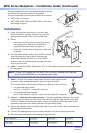
During installation ensure the space behind the device
is sufficient for the bend radius of the pigtail.
The recommended minimum bend radii are as follows:
z WPD 110A = 2.0 inches
z WPD 120A, WPD 130A and WPD 140A = 2.4 inches
(see image at right)
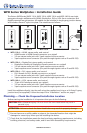
T
S
R
C
HDMI
A
B
C
Extron
WPD 110 A
Wall Mounting
Bracket
Decora
Faceplate
e
B
A
C
WPD 130 A
4.1"
(104 mm)
2.37"
(60 mm)
1.41"
(36 mm)
Installation
1. Using the supplied mud ring or a junction box
(not included) as a guide, mark and cut out the
appropriate material within the marked area.
2. Either:
z Insert the mud ring into the opening, rotate
the locking arms, and secure it with the
supplied screws (as shown at right), or
z Insert the junction box and secure it with nails
or screws.
3. Run the cables (video, audio, IR or RS-232 control)
from the output or input device locations (as
applicable), behind the wall, and to the WPD
location, then thread the cables through the mud
ring or junction box.
4. Video — Insert the HDMI, DisplayPort, DVI, or VGA cable connector into the connector
on the pigtail.
NOTE: If using a DVI display with the WPD 110A, connect a HDMIM-DVIDF adapter
(part number 26-617-01) and a separate audio cable.
5. Audio — Secure the output audio cable into the 3-pole captive screw
connector. Wire as described below (see the figure at right).
This may be easier to do before attaching the device to the mud ring.
z For balanced mono audio:
tip (T) = +, ring (R) = –, sleeve (S) = ground
z For unbalanced stereo audio:
tip (T) = left channel, ring (R) = right channel, sleeve (S) = ground
6. Control — 3-pole pass-through connector — Connect applicable cables to the 3-pole
captive screw connector on the rear of the WPD for pass-through signals, such as IR
or RS-232. When connecting the cables, ensure the polarity will be the same as the
proposed input device to avoid crossover and grounding issues.
7. Mount the cabled device into either the mud ring or the junction box and attach the
supplied Decora faceplate.
8. Connect the appropriate input or output devices to the front panel connectors.
9. Test the system and resolve any cabling or signal issues.