


TP T 15HD 45 and TP T A 45 • Installation
2-3
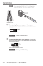
Å
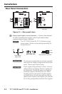
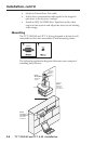
Captive screw digital audio input connector — Connect the
digital audio input cables from the TP T A 45 (if installed) to the
2-pole female direct insertion captive screw connector.
-
+
Digital Audio Input Captive Screw
Direct Insertion Connector
+
AUDIO
-
AUDIO
W
Remove power before wiring.
N
The wire gauge should be 14 - 22 AWG and the
maximum distance betwee the modules should not exceed
25 feet.
b
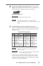
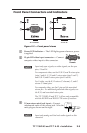
Video and audio output 8-pin spring force connector —
Attach a UTP cable from a TP receiver to the 8-pin spring force
connector. Wire this connector according to the following pin
assignment table.
Twisted Pair Pin Assignments
Pin Signal
1
2
3
4
5
6
7
8
red / vertical sync +
red / vertical sync - green orange
digital audio + white-orange white-green
green + blue blue
green - white-blue white-blue
digital audio - orange green
blue / horizontal sync + white-brown white-brown
blue / horizontal sync - brown brown
TIA/EIA T-568-A
Wire Color
white-green white-orange
TIA/EIA T-568-B
Wire Color
N
T-568-A is recommended when using an Extron
Skew-Free
™
cable.
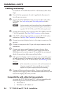
C
Do not connect the transmitter to a computer data
or telecommunications network.
Using a small screwdriver and observing the correct wiring
colors in the previous table, insert the stripped wire ends (see
note below) of the twisted pairs into the spring force connector,
as shown in the following diagram.