


TP T 15HD 45 and TP T A 45 • Installation
TP T 15HD 45 and TP T A 45 • Installation
Installation, cont’d
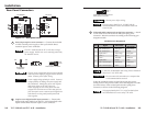
As a stand-alone transmitter, the TP T 15HD 45 is compatible
with:
• VTR001, VTR001 AAP, and VTR001 MAAP (RGBHV/RGBS
only)
• TPX 88
Cable testing
To ensure proper cable termination, each transmission cable
system that uses CAT 5e or CAT 6 cable should be tested
(Extron Skew-Free™ A/V UTP cable does not need to be
tested). Testing the cable from the transmitter and receiver
gives the most accurate indications of cable problems.
There are two varieties of cable runs: simple runs, in which a
single cable is terminated only at the transmitter and receiver,
and complex runs, which can include patch bays and multiple
terminations and lengths of cable. In either case, the entire
cabling system should be tested.
A complete test measures cable length and tests the wire map,
attenuation, NEXT, PSNEXT, ELFEXT, PSELFEXT, return loss,
ACR and PSACR. All of these tests are critical for digital data
transfer. While all of these tests are important indicators of the
quality of the cable termination, the most critical testing
parameters for video transfer are wire map (T-568-A or T-568-B
termination) and pair length measurements. The largest
concern is equalization of skew between cable pairs. Cable
systems of 300 feet or less should exhibit no transmission
problems if they pass at least CAT 5e or preferably CAT 6-D5
channel certification testing.
The Microtest OMNI SCANNER 2 performs comprehensive
certification testing to the proposed CAT 6 standards. Other
manufacturers also make testing equipment. The tests include
advanced diagnostics for troubleshooting the cause and location
of many cable and termination problems. For simple
installation testing, the Microtest MICRO SCANNER PRO tests
wire map and cable length, including individual cable pair
length.
2-72-6
2
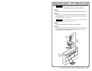
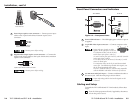
Connect the TP T 15HD 45 and its receiver to either end of
the UTP cable. See Cable testing and Skew delay problems in
this chapter.
For best results, use Extron Skew-Free™ A/V UTP
cable available in bulk or in various preterminated
lengths. If necessary, regular CAT 5, CAT 5e, and CAT
6 cable may be used.
3
Connect the external power supply to the TP T 15HD 45
and TP T A 45 (if installed). See Rear Panel Connectors in
this chapter.
4
If the TP T A 45 is being installed, connect the TP T A 45 to
the transmitter. See Rear Panel Connectors in this chapter.
5
Connect an output display device to the output connector
of the receiver.
6
Connect a computer to the 15-pin video input connector
of the transmitter.
7
Connect and power up all input and output devices, then
apply power to the TP T 15HD 45 power supply and test
for the display and/or audio outputs. If a problem is
encountered, check all connections before proceeding
further.
8
If the previous display and/or audio test was successful,
power off and disconnect all equipment, detach cables,
and install the TP T 15HD 45 and/or TP T A 45 modules.
See Mounting in this chapter.
If the transmitter or receiver is to be wall-mounted and
the power supply will be inaccessible, power must be
applied to the power supply before final mounting.
9
Connect all device and power cables. Power up all input
and output devices, apply power to the transmitter and
receiver, and test for the display and/or audio.
Compatibilty with other Extron products
As a pair, the TP T 15HD 45 and TP T A 45 are compatible with
the following Extron receivers and matrix switchers:
• TP R 15HD A
• TP R BNC A, TP R BNC AV
• TPX 88A