


RGB 203 Rxi • Setup Guide (Continued)
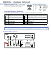
Step 8: Connect RS-232 Controller — Connect an RS-232
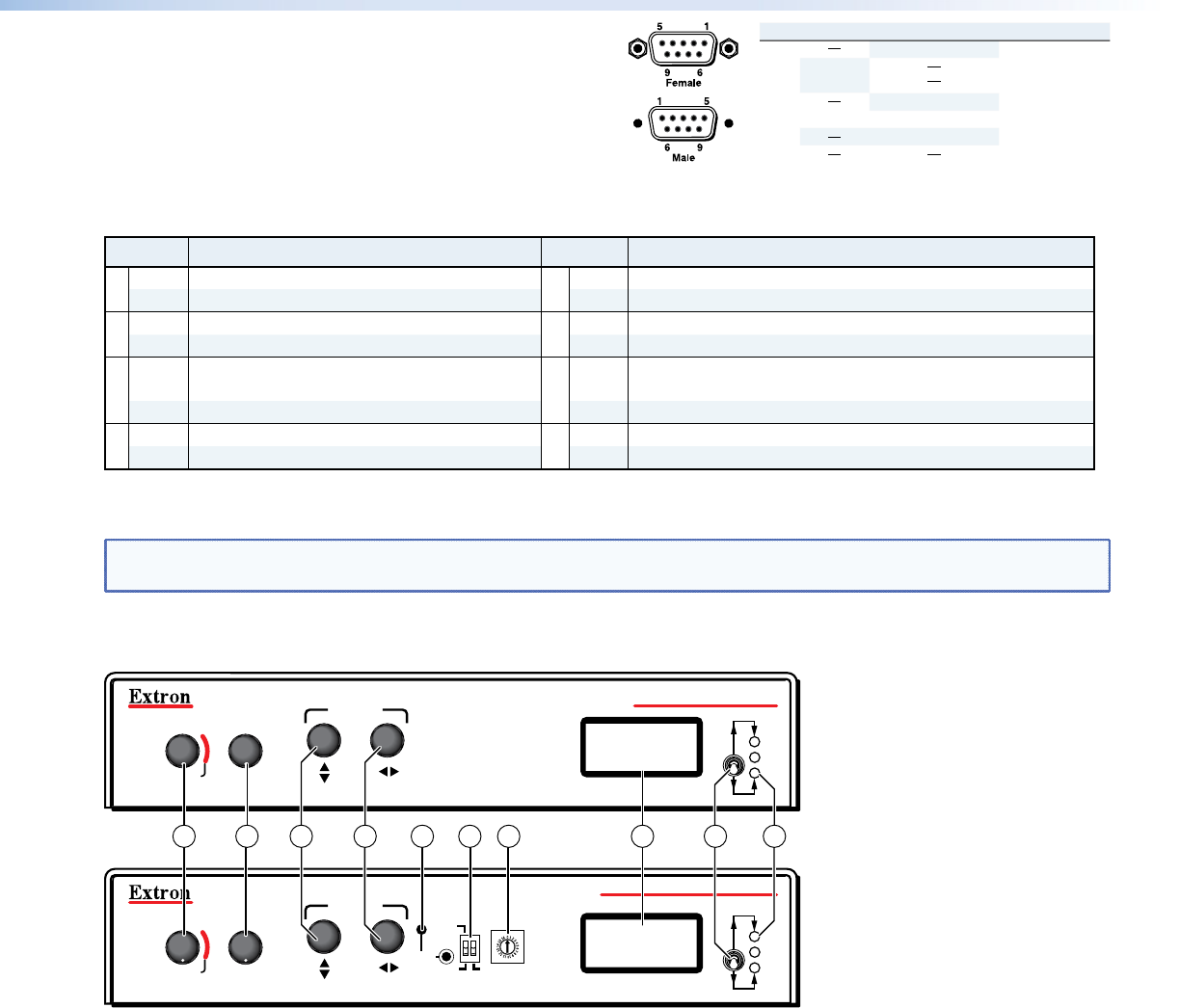
controller to this DB9 connector (
g
) for remote control. For
correct wiring, see the diagram and table at right.
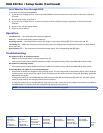
Rear Panel DIP Switch Conguration
Step 9: Set Rear Panel DIP Switches — Configure the rear panel DIP switches (
f
) as shown in this table.
Switch Effect Switch Effect
1 Up DDSP
™
, no sync processing 5 Up Monitor to input selection, Ground ID bits 4 and 11
Down ADSP
™
Down Monitor tied to in #1, ID bits unterminated
2 Up RGsB output 6 Up Mono or left channel audio
Down RGBHV or RGBS output Down Stereo audio
3 Up Serration pulses 7 Up Autoswitch to highest input number with sync signal
present
Down No serration pulses Down Autoswitching off
4 Up Narrow V sync pulse 8 Up LCD backlight off
Down Wide V sync pulse Down LCD backlight on
Step 10: Connect Power — Connect a standard IEC AC power connector (100-240 VAC, 50-60 Hz) to this socket (
h
).
NOTE: At this point, the ADSP model can be powered on and is ready for operation (see "Operation" on the back page
of this guide). For the EDID Minder model, see "Configuring EDID (EDID Minder Model Only)" below.
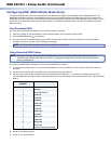
Front Panel Connections
RGB 203 Rxi
BOOST
LEVEL
CONTROL
PEAK
EDID
SELECT
50 Hz
RECORD
60 Hz SPARE
UNIVERSAL INTERFACE WITH EDID MINDER
CENTERING
INPUT
1
2
3
RGB 203 Rxi
BOOST
LEVEL
CONTROL
PEAK
INPUT
1
2
3
WITH ADSP
TM
CENTERING
9 10 11 12 16 17 1813 14 15
Pin RS-232 Contact ClosureFunction
1
2
3
4
5
6
7,8,9
Tx
Rx
Gnd
Input #1
Input #2
Gnd
Input #3
Input #1
Tr
ansmit data (-)
Receive data (+)
Signal ground
Input #3
Input #2
Not used