


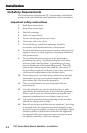
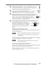
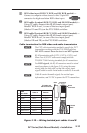
5
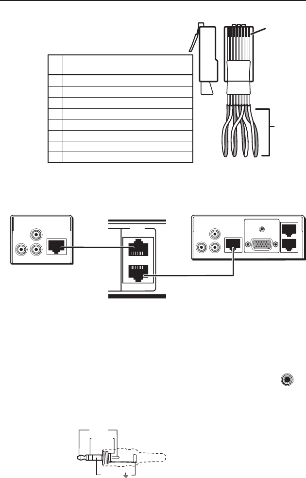
Pin
1
2
3
6
7
8
4
Wire color
White-green
Green
White-orange
White-blue
Orange
White-brown
Brown
568A
Blue
Composite
Video and Audio signal
Video +
Video –
+ 5 VDC
Audio L –
GND
Audio R +
Audio R –
Audio L +
Clip Down
Side
1
1&2
3&6 4&5
7&8
2345678
1Pins 2345678
RJ-45
connector
Twisted
pairs
TP Cable and
CAT 5 connector
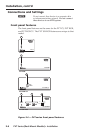
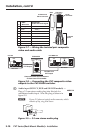
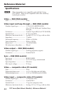
Figure 2-7 — Wiring the twisted pair composite
video and audio cable
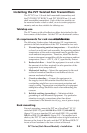
AUDIO
IN
VIDEO
IN
VIDEO OUT
L
R
PVT CV
4
3
VIDEO
TP cable from
PVT Output
PVS 204SA
Rear Panel
Composite Video Input Connectors
on Rear Panel of PVS 204SA
TP cable from
PVT Output
COMPUTER IN
AUDIO IN
AUDIO
IN
VIDEO
IN
VIDEO OUT
L
R
RGB B OUT
RGB A OUT
Rear Panel
PVT RGB CV
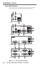
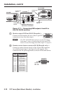
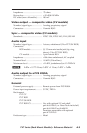
Figure 2-8 — Connecting the PVT composite video
outputs to the PVS 204SA switcher
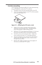
d
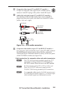
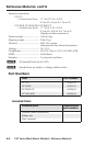
Audio input (RGB C�, RGB and SW RGB models) —
Plug a 3.5 mm stereo audio plug into this jack for
unbalanced audio input. Wire the plug as shown in
figure 2-9.
N Figure 2-9 shows a typical audio connector, which
consists of tip, ring, and sleeve.
Sleeve ( )
Ring (R)
Tip (L)
Figure 2-9 — 3.5 mm stereo audio plug
PVT Series (Rack Mount Models) • Installation
Installation, cont’d
2-10
AUDIO IN