


PVT Series (Rack Mount Models) • Installation
2-11
e
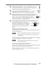
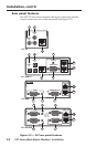
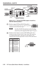
RGB video input (RGB C�, RGB, and SW RGB models) —
Connect a computer video source to this 15-pin HD
connector for high resolution RGB video input.
ä
RGB cable A output (RGB C�, RGB, and SW RGB models) —
Using TP cable, connect this RJ-45 female output port,
labeled "RGB A out", to one of the two input ports
(labeled 1A and 2A) on the PVS 204SA switcher.
ã
RGB cable B output (RGB C�, RGB, and SW RGB models) —
Using TP cable, connect this RJ-45 female output port,
labeled "RGB B out", to one of the two input ports
(labeled 1B and 2B) on the PVS 204SA switcher.
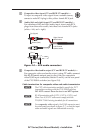
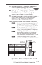
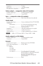
Cable termination for RGB video and audio transmission
N
The PVT cable termination method is specific for PVT
transmitters working with the PVS 204SA switcher.
DO NOT connect these devices to an MTP system.
N
RJ-45 termination with CAT 5, CAT 5e, CAT 6, and
Skew-Free A/V UTP cable must comply with the
TIA/EIA T 568A wiring standards for all connections.
N
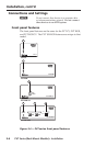
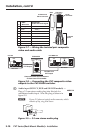
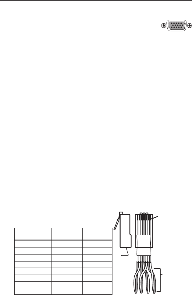
For RGB signals, the RJ-45 connectors must be wired
exactly as shown in the figure 2-10, using the same
wiring table for both ends, so that the correct input
signal (video on cable A and audio on cable B) is carried.
N
Cable B carries the audio signal, the vertical sync
information, and 5 VDC to power the PVT transmitters.
5
Pin
1
Red +
2
Red –
3
H. sync +
Green –
6 H. sync –
7
Blue +
8
Blue –
4
Wire Color
White-green
Green
White-orange
White-blue
Orange
White-brown
Brown
568A
Cable B
Green +
Blue
Cable A
V. sync +
V. sync –
+ 5 VDC
Audio L –
GND
Audio R +
Audio R –
Audio L +
Clip Down
Side
1
1&2
3&6 4&5
7&8
2345678
RJ-45
Connector
Twisted
Pairs
TP Cable and
CAT 5 Connector
1Pins 2345678
Figure 2-10 — Wiring twisted pair cables A and B