


QS-1
DVS 304 • Quick Start
FCC Class A Notice
This equipment has been tested and found to comply with the limits for a Class A digital device, pursuant to part 15 of the FCC Rules.
Operation is subject to the following two conditions: (1) this device may not cause harmful interference, and (2) this device must accept any
interference received, including interference that may cause undesired operation. The Class A limits are designed to provide reasonable
protection against harmful interference when the equipment is operated in a commercial environment. This equipment generates, uses,
and can radiate radio frequency energy and, if not installed and used in accordance with the instruction manual, may cause harmful
interference to radio communications. Operation of this equipment in a residential area is likely to cause harmful interference, in which
case the user will be required to correct the interference at his own expense.
N
This unit was tested with shielded cables on the peripheral devices. Shielded cables must be used with the unit to ensure compliance with
FCC emissions limits.
声明
所使用电源为 A 级产品,在生活环境中,该产品可能会造成无线电干扰。在这种情况下,可能需要用户对其干扰采取切实可行的措施。
Quick Start — DVS 304
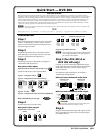
Installation
Step 1
Refer to the application examples at the end of this
section. If connected to a power source, turn off
power to the scaler, the input and out put devices,
and remove power cords.
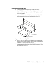
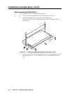
Step 2
Install the four rubber feet on the bottom of the
DVS 304 scaler, or mount the scaler in a rack (see
chapter 2 “Installation and Operation”).
Step 3
Attach input devices to the scaler (see chapter 2
“Installation and Operation”).
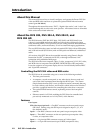
Rear panel video inputs
SDI input (DVS 304 D or AD models only)
SDI
Attach an SDI source to this optional BNC.
Input 1: Composite video
1
VID
Input 2: Composite/S-video/YUVi/YUVp
Composite Video
2
Y
/VID
B-Y
/C
R-Y
2
R-Y
Y
/VID
B-Y
/C
Component Video (Y, R-Y, B-Y)
2
B-Y
/C
S-video (YC)
Y
/VID
R-Y
Input 3: S-video
3
YC
Input 4: Composite/S-video/YUVi/YUVp/RGBcvS/
RGB scaled/RGB pass through
RGB/R-Y,Y,B-Y/YC/VID
4
Step 4
Attach output devices to the scaler.
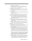
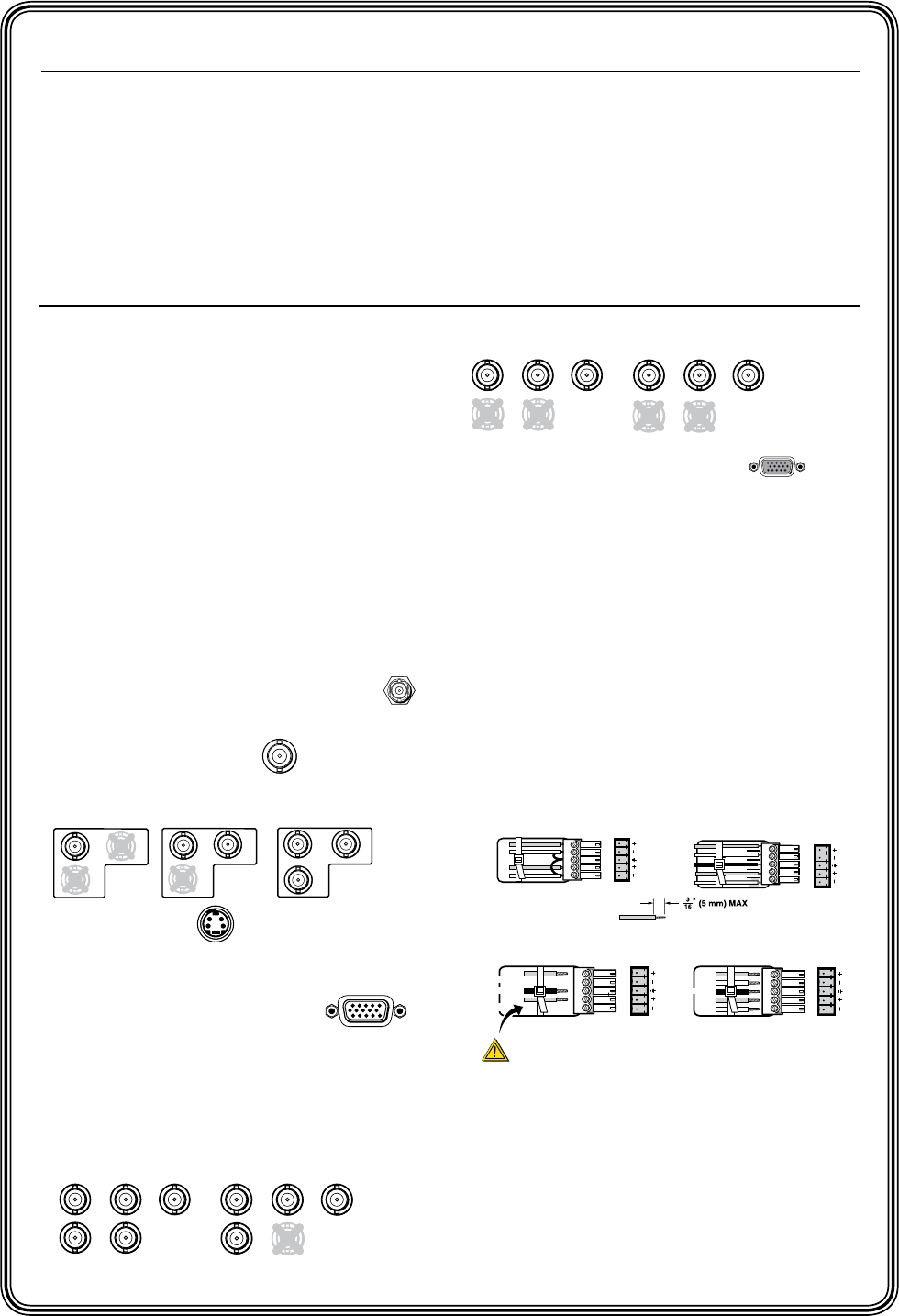
Rear panel video outputs
Output BNC connectors
RGBHV
H/
HV
R
/R-Y
V
G
/Y
B
/B-Y
R
/R-Y
G
/Y
B
/B-Y
RGsB
H/
HV
V
R
/R-Y
V
G
/Y
R
G
B
S
H/
HV
B
/B-Y
B
/B-Y
Component Video (Y, R-Y, B-Y)
R
/R-Y
G
/Y
H/
HV
V
RGBHV
H/
HV
R
/R-Y
V
G
/Y
B
/B-Y
R
/R-Y
G
/Y
B
/B-Y
RGsB
H/
HV
V
R
/R-Y
V
G
/Y
R
G
B
S
H/
HV
B
/B-Y
B
/B-Y
Component Video (Y, R-Y, B-Y)
R
/R-Y
G
/Y
H/
HV
V
Output 15-pin HD connector
N You can connect both outputs simultaneously
to two different displays. The sync format is
the same for both outputs.
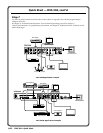
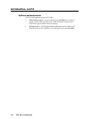
Step 5 (for DVS 304 A or
DVS 304 AD only)
Connect up to four balanced or unbalanced stereo
audio input devices to the DVS 304 as shown below.
Each audio input has a 3.5 mm, 5-pole captive
screw connector.
For detailed wiring instructions, see chapter 2
“Installation and Operation”.
Balanced and unbalanced audio input
Tip
Ring
Tip
Ring
Sleeves
Balanced Input
(high impedance)
L R
AUDIO
Tip
Sleeve
Tip
Sleeve
L R
AUDIO
Unbalanced Input
(high impedance)
Do not tin the wires!
Balanced and unbalanced audio output
Tip
Tip
L R
AUDIO
Tip
Ring
Tip
Ring
AUDIO
L R
Unbalanced Stereo Output
Balanced Stereo Output
CAUTION
For unbalanced audio, connect the sleeve(s) to the center contact ground.
DO NOT connect the sleeve(s) to the negative (-) contacts.
Sleeve (s)
See Caution
Sleeve (s)
See Caution
Step 6
Plug the DVS 304, and the input and output devices
into a grounded AC source, then turn on the input
and output devices.
RGB