


DVI DL 201 Tx/Rx • Installation
2-15
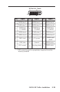
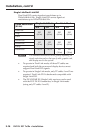
Pin #
TIA/EIA
T 586 A
Wire color
TIA/EIA
T 586 B
Wire color
Cable 1 Cable 2 Cable 3
1 White-green White-orange Data 0+ CEC Data 3+
2 Green Orange Data 0+ HPD Data 3+
3 White-orange White-green IDCK+ RS-232 Tx/IR+ N/C
4 Blue Blue Data 1+ DDC Clock Data 4+
5 White-blue White-blue Data 1+ +12 V Data 4+
6 Orange Green IDCK- RS-232 Rx N/C
7 White-brown White-brown Data 2+ DDC Data Data 5+
8 Brown Brown Data 2+ Ground Data 5+
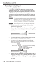
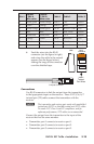
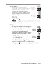
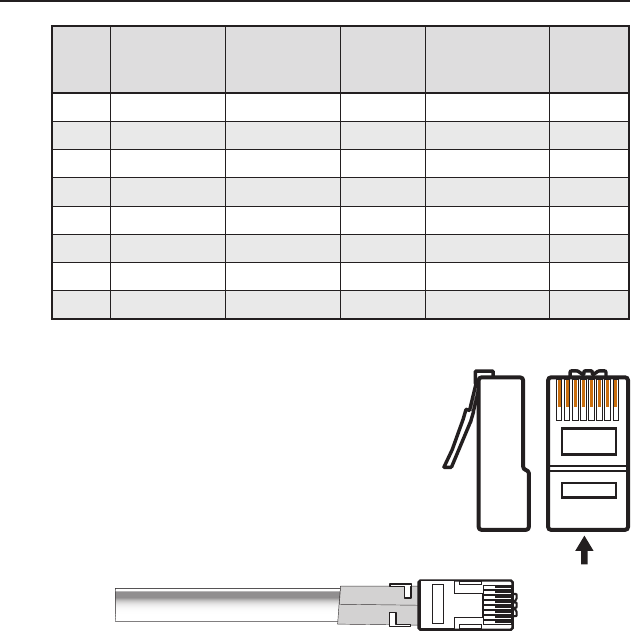
6. Feed the wires into the RJ-45
connector (see the gure at right)
and crimp the cable in the normal
manner (see the gure below),
folding the tangs of the connector
over the shielded tape.
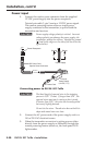
Crimped Connector
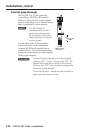
Connections
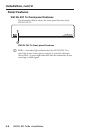
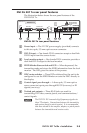
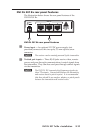
Use RJ-45 connectors to link the output from the transmitter
to the appropriate input on the receiver. Three CAT 5/5e/6/7
twisted pair (TP) cables connect the transmitter with the
receiver.
N
The transmitter and receiver pair works with unshielded
twisted pair (UTP) or shielded twisted pair (STP) cables.
To ensure FCC Class A and CE compliance, and for
optimum performance, STP cables are recommended.
Connect the output from the transmitter to the input of the
receiver that has the same number:
Transmitter port 1 connects to receiver port 1.•
Transmitter port 2 connects to receiver port 2.•
Transmitter port 3 connects to receiver port 3.•
Side
12345678
Insert
Twisted
Pair Wires
Pins:
RJ-45
Connector