


Receiver Connections
.
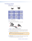
DTP HDMI 301 Rx Rear Panel
DTP
HDMI
30
1
R
x
R
ear
P
ane
l
Front Panel
OUTPUTS
L R
AUDIO
POWER
12V
0.6 A MAX
IN
ANALOG AUDIO
SIG LINK
DTP IN
o
nt
P
ane
l
F
r
o
R
RxTx
RS-232 IR
RxTx
DTP HDMI 301 Rx
6 98
10 7
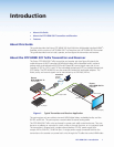
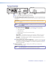
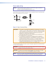
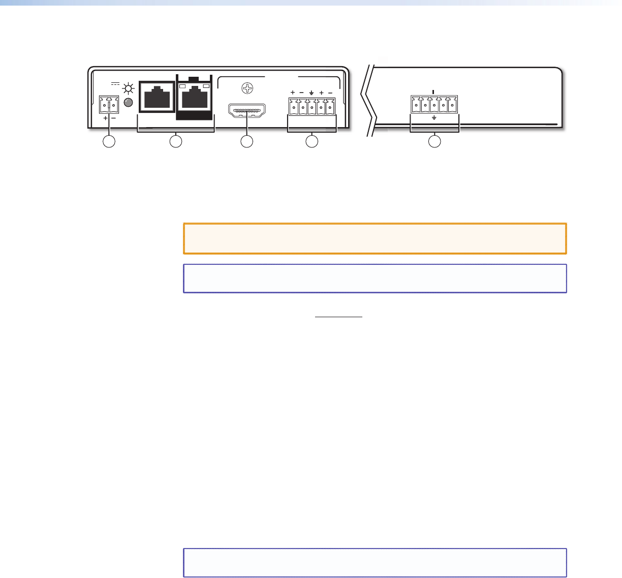
Figure 3. DTP HDMI 301 Rx Rear Panel Connectors
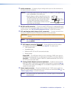
f DTP and Analog Audio Input RJ-45 connectors — Connect one end of the one
or two separate TP cables from the transmitter output connectors to these RJ-45 female
connectors.
CAUTION: Do not connect this device to a computer data or telecommunications
network.
NOTE: See “TP cable termination“ to properly wire the RJ-45 connectors and for
detailed NOTES.
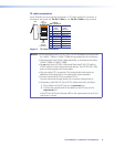
ä DTP Input connector (Required) — Ensure the free end of this cable is
connected to the transmitter DTP Out connector (item
Ü
). This cable carries:
• TMDS (digital) video
• Embedded audio
• Bidirectional RS-232 and IR commands and data
• Remote power
Signal LED — This LED lights when the unit is receiving a TMDS clock signal on
the DVI input (transmitter) or any valid signal on the DTP In connector (receiver).
Link LED — This LED lights when a valid link is established between the units on
the DTP input and output cable.
ã Analog Audio Input connector (Optional) — If desired, ensure the free end
of this cable is connected to the transmitter Analog Audio Out connector (item
á
).
This cable carries analog audio only and is not needed for applications that do not
require this audio signal.
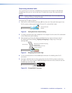
g Output connector — Connect a display with an HDMI input to display the
transmitted direct digital image.
NOTE: See “HDMI connector“ for pin assignments and to use the LockIt HDMI
Cable Lacing Bracket to secure the connector to the receiver.
DTP HDMI 301 • Installation and Operation 5