


2
DMP128 • Setup Guide (Continued)
f
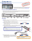
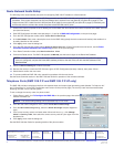
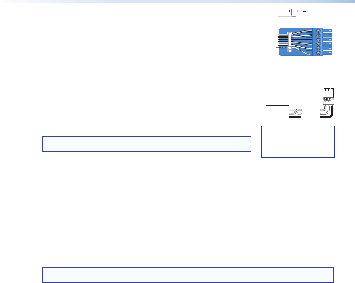
Digital I/O connectors — Connect up to four 6-pole 3.5 mm captive screw connectors. Each
connector provides ve congurable digital input or output ports allowing connection of up to
twenty devices such as motion detectors, alarms, lights, LEDs, buttons, photo (light) sensors, and
temperature sensors.
Digital I/O ports can monitor or drive TTL level digital signals. The inputs are congured to
operate in one of two modes: digital input or digital output. In output mode, the device sources
up to 250mA at +5 V. In input mode, voltages greater than 1 V indicate a logic ‘high’ signal while
voltages less than 1 V indicate a logic 'low'.
Digital I/O ports are tied to a common ground (one common ground for each 6-pole connector).
g
Connect a control system — There are three options to connect a control system to the DMP128: LAN, RS-232, and USB
(front panel only). Extron recommends using the LAN port for conguration and remote control of the DMP128.
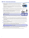
RS-232 — Connect the host RS-232 cable to the rear panel of the switcher (
å
) using the
provided 3-pole captive screw connector for bi-directional RS-232 (±5V) serial control. The
default baud rate is 38400. Use the wiring diagram at right.
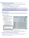
LAN — Using a standard Ethernet cable, connect to a network via the LAN port (
ç
). The
table at right shows the default network settings. The control system and DMP128 must be
connected on the same network.
NOTE: To connect the DMP128 directly to a computer Ethernet port, use a
crossover Ethernet cable.
USB — Connect the host USB port to the front panel conguration port, (notshown), using a
USB A to mini-B cable. The USB connection is used only for conguration. Use the RS-232 or LAN port for remote control of
the DMP128.
h
EXP port connector — One RJ-45 jack for digital audio connection to an additional DMP128 using the Extron proprietary
protocol. Use the included one foot long shielded CAT6 cable to connect two DMP128 units to form a larger matrix system.
The expansion bus supports 16bi-directionalchannels of audio; eight assignable channels that are mixed from any of the
input and virtual paths, and eight channels directly connected to the virtual return path outputs. See the DMP128 User Guide
for operation details.
i
Reset button and LED indicator — The reset button returns the DMP128 to different tiers of default states and places the
unit into an event recording mode for troubleshooting. The LED ashes to signify the different tiers (see “DMP128 Hardware
Reset Modes” in the DMP128 User Guide).
j
AT ports (AT models only) — Four RJ-45 jacks form a 4-port Gigabit switch that interfaces with the ATbus. The
ATexpansion bus uses the Dante™ protocol for digital media networking allowing connection of multiple DMP128AT
models to form a larger matrix. See the DMP128 User Guide for operation details.
NOTE: The Dante Controller software is required for configuration of the AT expansion bus (see Dante Controller
Software Installation (AT models only) on the next page).
k
Telephone ports (P models only) — Two RJ-11 jacks for incoming line (LINE) and telephone (PHONE) connection.
The telephone interface follows all applicable US standards and international standards for select countries. A phone dialer is
available in the DSPCongurator control software to assist with setup and testing.
When all connections have been made, power up the input and output devices, then apply power to the DMP128.
Receive (Rx)
Transmit (Tx)
Ground ( )
Bidirectional
RS-232
Device
Ground ( )
Receive (Rx)
Transmit (Tx)
RxTx G
G G
Do not tin
the wires!
IP Address: 192.168.254.254
Subnet Mask: 255.255.0.0
Default Gateway: 0.0.0.0
DHCP: OFF
Do not tin the wires!
(5 mm) MAX.
3 "
16
1
2
3
4
5
G
Digital I/O Wiring