


5
Chapter II Back Panel Function
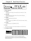
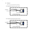
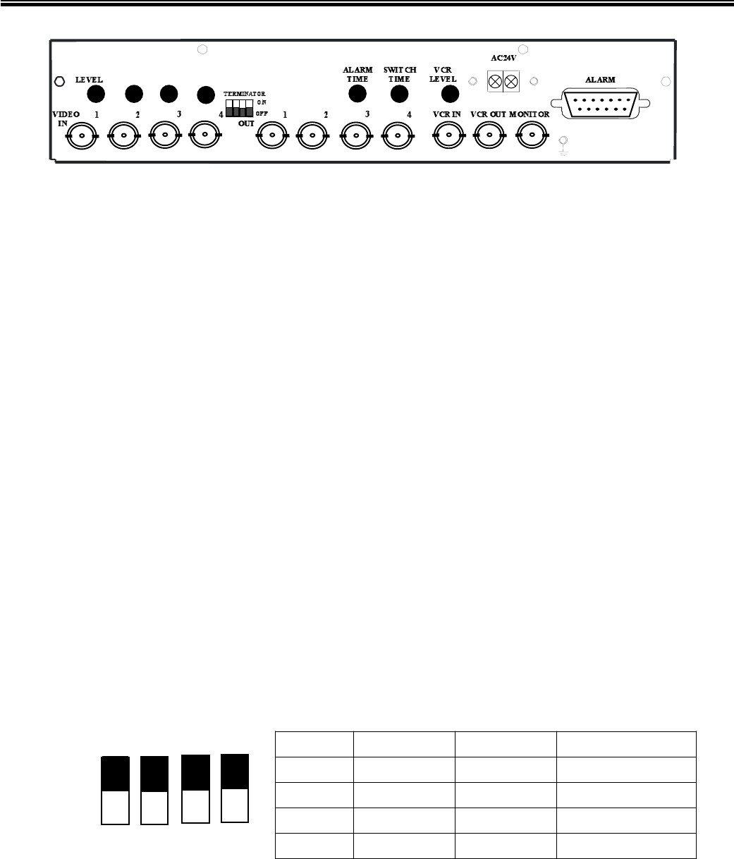
1. BNC Connectors
1.1 Video In
Connect camera video output to the corresponding video in connector by a 75 ohm
coaxial cable.
1.2 Video Out
Connect the other devices to these connectors. They are used to loop through
camera’s video to other devices.
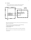
1.3 Monitor
Connect this output port to the main monitor.
1.4 VCR Out
Connect this output port to the VIDEO IN of VCR. The quad video output is obtained
from this connector.
1.5 VCR In
Connect this input port to the VIDEO OUT of VCR.
2. Level
The 4 gain control regulators is used to adjust the brightness level of the video input.
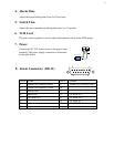
3. Terminator On/Off
ON
1 2 3 4
Each camera should be terminated by 75 Ohms. This termination is normally
provided by having all switches of 1-4 on. If cameras are looped through to other
equipment which provides termination, then the switch sections of the corresponding
inputs should be turned off.
Terminator Camera Input OFF ON
1 1 Not Terminated 75 Ohm Termination
2 2 Not Terminated 75 Ohm Termination
3 3 Not Terminated 75 Ohm Termination
4 4 Not Terminated 75 Ohm Termination