


406-512 MHz MASTR II RECEIVER
ICOM FREQUENCY ADJUSTMENT
First, check the frequency to determine if any adjustment is required. The frequency measurement requires equipment with an
absolute accuracy which is 5 to 10 times better than the tolerance to be maintained. When performing frequency measurement, the
entire radio should be as near as possible to an ambient temperature of 26.5°C (79.8°F).
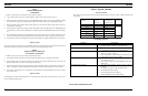
MASTR II ICOMs should be reset only when the measured frequency error exceeds the following limits.
A.
±0.5 PPM, when the radio is at 26.5°C (79.8°F).
B.
±2 PPM at any other temperature within the range -5°C to +55°C (+131°F).
C.
The specification limit (±2 PPM or ±5 PPM) at any temperature within the ranges -40°C to -5°C (-40°F to +23°F) or +55° to
+70°C (+131°F to +158°F).
If frequency adjustment is required, lift up the cover on the top of the ICOM (where present) to expose the adjustment trimmer.
Depending upon the type of frequency measuring equipment that is available, any of the following procedures may be used:
A.
DIRECT MEASUREMENT IN THE INJECTION CHAIN
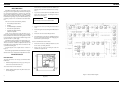
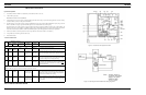
1. WITH A FREQUENCY COUNTER. "Count" the frequency at the junction of C416 and L403 on the Oscillator/Multiplier
Board. The frequency measured at this point is 9 times the ICOM frequency. NOTE: The output from the ICOM itself is
not sufficiently sinusoidal for reliable operation with most frequency counters.
2. WITH A COMMUNICATION MONITOR (for example: Cushman Model CE-3). "Monitor" frequency at the junction of
C416 and L403 on the Oscillator/Multiplier Board. The frequency monitored at this point is 9 times the ICOM frequency.
NOTE: This frequency will not always fall within an available measuring range of all monitors at all receiver operating
frequencies.
B.
STANDARD "ON FREQUENCY" SIGNAL AT THE RECEIVER INPUT (Generated from a COMMUNICATION MONI-
TOR, for example: Cushman Model CE-3).
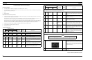
1. WITH A FREQUENCY COUNTER. "Count" the developed IF frequency at the top of Z602-R2 on the IFAS board. The
deviation from the nominal IF frequency (11.2 MHz) in Hz is compared to the receiver operating frequency (also in Hz)
to calculate error in PPM.
2. WITH AN 11.2 MHz IF FREQUENCY STANDARD (for example: Model 4EX9A10). Loosely couple the IF frequency
standard to the IF signal path to create a heterodyne with the developed IF frequency. The resultant "beat frequency" can
be monitored by either of the following methods:
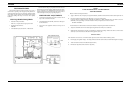
a. Audible "beat frequency" from the receiver speaker (this requires careful frequency adjustment of the frequency standard).
b. Observe "beat frequency" at P904-4 with an Oscilloscope.
c. With TEST SET (Meter Position B) connected to J601 on the IFAS Board, visually observe the "beat frequency" indicated
by meter movement.
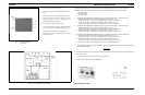
To SET ICOM frequency using "beat frequency" method, the temperature should be at 26.5°C (79.8°F). If the temperature
is not 26.5°C, then offset the "on frequency" signal (at the receivers input), as a function of actual temperature, by the
frequency error factor (in PPM) shown in Figure 7.
NOTE
The frequency of the "beat" is the frequency error, related to the IF frequency. This deviation, in Hz, is compared to the
receiver operating frequency, also in Hz, to calculate the error in PPM.
If the radio is at an ambient temperature of 26.5°C (79.8°F), set the oscillator for the correct mixer frequency (ICOM FREQ.
X 9).
If the radio is not an ambient temperature of 26.5°C, setting errors can be minimized as follows:
A.
To hold setting error to ±0.6 PPM (which is considered reasonable for 5 PPM ICOMS):
1.
Maintain the radio at 26.5°C (±5°C) and set the oscillator to require mixer injection frequency, or
2.
Maintain the radio at 26.5°C (±10°C) and offset the oscillator, as a function of actual temperature, by the frequency
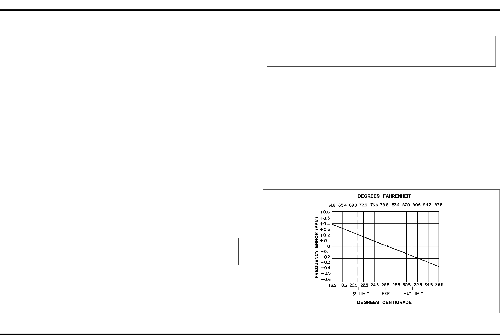
error factor shown in Figure 7.
B.
To hold setting error to ±0.35 PPM (which is considered reasonable for 2 PPM ICOMS): Maintain the unit at 26.5°C
(±5°C) and offset the oscillator, as a function of actual temperature, by the frequency error factor shown in Figure 7.
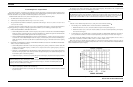
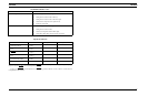
For example: Assume the ambient temperature of the radio is 18.5°C (65.4°F). At that temperature, the curve shows a
correction factor of 0.3 PPM. (At 138 MHz, 1 PPM is 138 Hz. At 174 MHz, 1 PPM is 174 Hz).
With a mixer injection of 150 MHz, adjust the oscillator for a corrected mixer injection frequency 45 Hz (0.3 X 150 Hz)
higher. If a negative correction factor is obtained (at temperatures above 26.5°C), set the oscillator for the indicated PPM lower
than the calculated mixer injection frequency.
The FM Detector output (meter position A of the test set) has a DC voltage of +0.35 to 0.5-Volts with an
ON-FREQUENCY signal or under NO-SIGNAL conditions and is provided for routine test and measurement only. The
resolution of this reading (approximately .025 V per kHz as read on a Test Set in meter position A, or 0.1 V per kHz as
measured with a VTVM at P904-3 or J601-2 on the IFAS board) is inadequate for oscillator frequency setting.
NOTE
Figure 7 - Frequency Characteristics Vs. Temperature
LBI-38505 LBI-38505
5