


3. Move the cursor to "OK" on the screen and push the Menu/Select button
on the main unit or the OK button on the remote control.
Pairing will start. The image of the documemt camera displays automatically
when pairing finishes.
If the pairing stops please turn the power of VP receiver power off
and the document camera, and restart pairing.
4. If you wish to register more than 1 document camera, repeat form step 1.
(Up to eight document cameras can be paired).
Caution
・For details about the operation of the Visual transmitter, refer to the instruction manual of the respective
Visual transmitter.
■Remove the visual transmitter
1. Select “Setup”. Then press the Menu/Select button
on the main unit or the OK button on the remote control.
2. Select “Remove Video Source” from the menu. Then press the Menu/Select
button of the main unit or the OK button of the remote control.
3. Select the name of Visual transmitter to remove. Then press the Menu/Select
button of the main unit or the OK button of the remote control.
4. Select “OK” and press the Menu/Select button
or the OK button of the remote control.
5. The confirmation of "Removing ○ ○ ○(Name of the transmitter) " appears,
then select OK and press the Menu/Select button
on the main unit or the OK button on remote control.
■Modify the name of the visual transmitter
1. Select “Setup”. Then press the Menu/Select button.
2. Select “Modify Video Source Name” from the menu.
Then press the Menu/Select button on the main unit
or the OK button on the remote control.
3. Select the registered visual transmitter. Then press the Menu/Select
button on the main unit or the OK button on the remote control.
4. (Using the main unit) Use the Up or Down buttons to move the cursor
left and right to the character you want to change. Press the Menu/Select
button and cursor will change colour to confirm selection. Now use
the up and down buttons to move to the new character you want to replace
the old one with and press the Menu/Select button to confirm.
(Using the remote control) This is the same procedure as the main unit,
but use the remote control left or right button to move the cursor,
the up or down buttons to change the character
and press the OK button to confirm.
5. Once completed press and hold the Menu/Select button on the main unit
or press the OK button on the remote control. Then select “Save”
and press the Menu/Select button on the main unit or the OK button
on the remote control.
Selecting the Video Source
Display the menu by pressing the Menu/Select button.
A list of registered visual transmitters appears in the menu. Select the desired visual transmitter.
Press the Menu/Select button to output the image of the selected visual Transmitter.
In addition, by pressing the Input button on the remote control
you can output video by selecting the video transmitter registration.
When the message of “Please remove and register this ○○○ again” is shown while linking with the transmitter, please
remove and add the transmitter again.
Info Menu
Push the Info button on the remote control, to display the current link status.
The registered name of the video transmitter and signal strength
of the video is displayed on the transmitter.
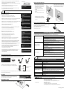
Receivable range
Distance: Within approx. 7m from the front of the infrared sensor
Angle: Within 30° up, down, left, and right of the infrared sensor
How to wall mount this unit
If you install on a wall as shown below, please install with standard screws (not supplied).
How to ceiling mount this unit
If you install on a ceiling, please connect the tripod screw holes
on the bottom of this unit to a ceiling mount bracket (not supplied).
At this time, to allow remote control operation
from a predetermined position,
please install with the infrared receiver of the main unit facing
towards the remote control.
TROUBLESHOOTING
If trouble occurs or you have any queries, first check this section.
If the problem persists, check your warranty and contact the dealer where you purchased the product.
The AC adapter is disconnected. Check the connection between the AC adapter and
the wall outlet.
Is the visual transmitter registered?
Add the visual transmitter.
Equipment which uses the same frequency may cause radio interference.
Check the surrounding radio frequency environment.
The VP Receiver does not work.
The AC adapter is disconnected from the VP Receiver.
Check the connection between the AC adapter and the VP Receiver.
HDMI cable is not connected properly.
Firmly insert HDMI cable into the connector.
The cable is damaged.
Do not use a damaged cable. (Replace the cable)
The input signal is out of the display range of the visual transmitter.
Check the resolution.
No image is displayed.
or
The image is distorted.
Equipment which uses the same frequency may cause radio interference.
Check the surrounding radio frequency environment.
HDMI cable is not connected properly.
Firmly insert HDMI cable into the connector.
The cable is damaged.
Do not use a damaged cable.
No audio from the visual transmitter is input.
No sound is output when there is no audio input.
No sound is output.
The volume of the visual transmitter or the image output device is set to minimum.
Turn up the volume.
Caution
・When error messages appear, follow the instructions to fix the error.
・If the problem persists, the product may be defective. Contact the dealer where you purchased the product
for repair.
PRODUCT SPECIFICATIONS
Operating Temperature 0℃ - 40℃ (32°F – 104°F)
Wireless Band Used 5190MHz - 5670MHz
Communication Distance
Approx. 10m (32.8feet)
(differs depending on the usage conditions)
Power Supply
AC adapter
Input: 100V-240V, 50/60Hz(0.3A)
Output: 5V, 2A
Standards HDMI / WHDI standard compliance, including HDCP
Transmitter registration 8 sets
Image output:
VGA (640x480)60Hz/75Hz, SVGA (800x600)60Hz/75Hz, XGA (1024x768) 60Hz/75Hz,
WXGA (1280x768) 60Hz, WXGA (1280x800) 60Hz, SXGA (1280x1024) 60Hz/75Hz
1152x864 (60Hz), 1280x960(60Hz) 480p, 576p, 720p, 1080i, 1080p
HDMI OUT (Type A)
Audio output: 192 kHz x 24 bit
Power Consumption (Current) 7W( 5V / 1.4A) without AC adapter
External Dimensions
L83 x W80 x H31 (mm)
L3 1/4” x W3 1/8” x H1 1/4”
Weight 110g (0.24lb)
6-14, Meizen-cho, Mizuho-ku, Nagoya, 467-8567, Japan
ELMO Europe SAS
Headquarters Immeuble Elysées La Défense, 7C Place du Dôme,
92056 Paris La Défense, FRANCE
Tel: +33 (0) 1 73 02 67 06 Fax: +33 (0) 1 73 02 67 10
E-mail:
info@elmoeurope.fr Web: http://www.elmoeurope.com/
German Branch Hansaallee 201, Haus 1
40549 Düsseldorf, Germany
Tel: +49 (0)211 544756 40 Fax: +49 (0)211 544756 60
E-mail: info@elmo-germany.de Web: http://www.elmo-germany.de/
VPR-2(E2)_M R0-Xex
CAMERA 1
CAMERA 2
CAMERA 1
CAMERA 2
7m
50mm
Pairing Button
The side panel of the MO-1w
Selection order of the
transmitter
VP Receiver
Push
Signal strength
Name of the video transmitter
Wall Mount screws are not included.
Please use the screws as shown below.
The screw head should be about 5mm
from wall.
When mounted to wall, the remote control
operation range is 30 ° left and right , 30 °
to the front wall as shown in the figure.
Please attach the screws to the wall.
When attached to the wall of the hollow
wall material such as gypsum board,
please use the plug anchor
corresponding to each of the wall
material.
The distance between screw and screw
is 50mm.
Then hook the screw hole on the unit.
Wall
Floor
8~9mm
Approx.
5mm
4mm