


DESCRIPTION
First of all, we would like to express our thanks and at the same time congratulate you on the decision to buy one of our Q-SERIES
power amplifiers.
ElectroVoice Q-SERIES amplifiers are made to meet the highest requirements of any on-the-road application. Thus they provide
on-board protection against thermal and capacitive overload, short-circuit and the occurrence of HF or DC at the output.
Additionally, special circuitry prevents the output-stage transistors from being damaged by Back-EMF. During soft start, delayed
switching of the power outputs is accomplished via relays and a limiter controls the initial current inrush, preventing the mains
fuse from being blown during the power-on operation.
The mechanical construction as well is carried out following the highest precision standards of the industry. The robust steel chassis
provides extreme rigidity and it is meant to live through any hard wearing condition of a touring application. Thermal stability is
guaranteed by two 3-Mode silently running fans that offer the possibility to also use the amplifiers in a studio environment.
The extensive comparator circuitry constantly monitors the input and output signals and activates the internal limiters whenever
a non-linear operational state is encountered. This provides reliable protection of the connected loudspeaker systems against
overload and clipping. The sound quality of the Q-SERIES power amplifiers is superb. Using comprehensive dimensioned power
supply units with low-interference toroidal transformers gains a headroom that exceeds the nominal power handling capacity by
far. No V/I-Foldback-Limiter circuits are employed within the power amplifiers, making it possible to operate the amps on complex
loads up to ±90° phase angles without a problem.
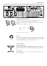
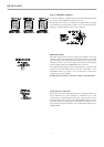
The input facilities are carried out as balanced XLRF-type sockets while the Direct-Outs – on which the carried-through signals
are present – come as XLRM-type connectors. Using the Input Routing-switches lets you determine if the Q-SERIES amplifiers
are operated in DUAL (stereo) or PARALLEL (monaural) mode; “mono-bridged” operation is also possible.
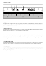
The dB-scaled level controls are to be found on the rear panel. These potentiometers guarantee precise and reliable operation. The
easy readable LED display on the front panel offers quick optical information on the power amplifiers’ momentary operational
mode. For each channel individually the display shows whether they are operational, a signal is present at the outputs, when the
limiters are activated, and whether one of the protection circuits has been engaged or not. The power outputs CANNEL A,
CHANNEL B and BRIDGED OUT are carried out as Speakon connectors. A ground-lift switch that separates the enclosure from
the appliance’s ground potential and therefore helps to eliminate ground noise loops and the mono bridged mode switch are also
located on the rear panel. In normal operation all Q-SERIES power amplifiers can be used to drive loads down to 2 ohms; in bridged
mode the minimal load is 4 ohms. All amps are equipped with extremely silent running fans providing front-to-rear air circulation,
guaranteeing trouble-free operation even in smaller power amplifier rack systems.
Studying this owner’s manual carefully will provide you with further and more detailed information about the Q-SERIES power
amplifiers. Thus we recommend to keep on reading, assuring you that the Electro Voice Q-SERIES power amplifiers will provide
you with a lot of fun and satisfaction in your work.
CONTENTS
Description . . . . . . . . . . . . . . . . . . . . . . . . . . . . . . . . . . . . . . . . . . . . . . . . . . . . . . . . . . . 3
Front Panel . . . . . . . . . . . . . . . . . . . . . . . . . . . . . . . . . . . . . . . . . . . . . . . . . . . . . . . . . . . 4
Rear Panel. . . . . . . . . . . . . . . . . . . . . . . . . . . . . . . . . . . . . . . . . . . . . . . . . . . . . . . . . . . . 5
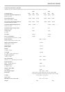
Specifications . . . . . . . . . . . . . . . . . . . . . . . . . . . . . . . . . . . . . . . . . . . . . . . . . . . . . . . . . 7
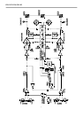
Block diagram . . . . . . . . . . . . . . . . . . . . . . . . . . . . . . . . . . . . . . . . . . . . . . . . . . . . . . . . 8
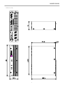
Dimensions. . . . . . . . . . . . . . . . . . . . . . . . . . . . . . . . . . . . . . . . . . . . . . . . . . . . . . . . . . . 9
Warranty. . . . . . . . . . . . . . . . . . . . . . . . . . . . . . . . . . . . . . . . . . . . . . . . . . . . . . . . . . . . . 12
DESCRIPTION
3