PROFESSIONAL POWER AMPLIFIER
10 Owner‘s Manual
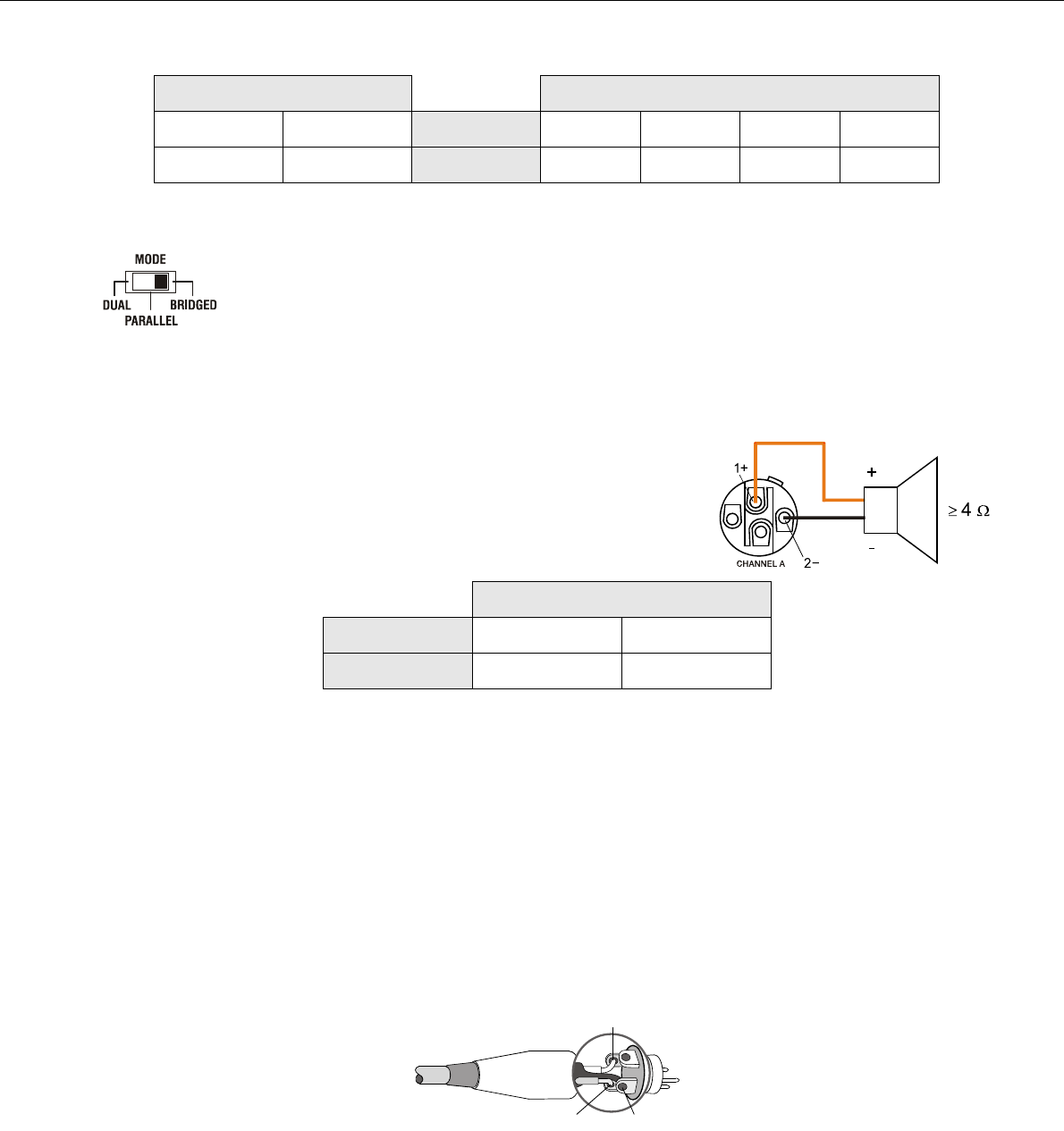
BRIDGED
In BRIDGED mode both amp channels work in push-pull operation to provide doubled output voltage. The
audio signal has to be applied to the input connectors of channel A, amplification is set via input level
control of channel A only.
In bridged mode operation speaker connection has to be established using pins 1+
and 2- of the Speakon socket CHANNEL A, see illustration right. The correct
connection is also indicated at the amplifiers rear panel.
2.9 Audio Input Cabeling
Inputs INPUT A and INPUT B are electronically balanced. The pin-assignment of XLRF-type connectors is in accordance with
the IEC standard 268.
Whenever possible, using balanced audio signal feeds at the input of the power amplifier is always preferred. Unbalanced
connections should only be used if the cables are very short and no interfering signals are to be expected in the vicinity of the
power amplifier. In this case, bridging the screen (shielding) and the pin of the inverting input inside of the connector is
Speakon CHANNEL B Speakon CHANNEL A
1+ 1-
Connector 1+ 1- 2+ 2-
B+ B-
Signal A+ A- B+ B-
Table 2.1: Speaker connection using Speakon A and B connectors
CAUTION:
In BRIDGED mode, the input signal has to be fed to input channel A only. Amplification is set
via input level control of channel A only.
Speakon CHANNEL A
Anschluss 1+ 2-
Belegung Bridged+ Bridged-
Table 2.2: Speaker connection using Speakon A
CAUTION:
In BRIDGED mode operation, it is not allowable for the load connected to fall below a value of
4 ohms. Extremely high voltages can be present at the output. The connected speaker sy-
stems must be able to handle such voltages. Make sure to completely read and fully observe
power rating specifications of the speaker systems to be used and to check them against the
output power capacity of the power amp.
Illustration 2.1: Balanced connection of input
1, SHIELD
3, COLD
2, HOT


