


7
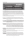
INPUT A / INPUT B
This indicator lights as soon as the integrated dynamic
limiter is activated and the power amplifier is driven at
the clipping limit or generally at its maximum
capacity. Short-term blinking is not a problem, since
the internal limiter trims input levels of up to +21dBu
down to a S/N-ratio of approximately 1%. If, on the
other hand, this LED lights constantly, reducing the volume is recommended to prevent the loudspeak-
er systems connected from being damaged by probable overload
.
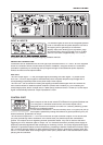
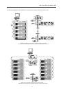
PARALLEL CONNECTION
Connection can be established via the XLR-type input connectors INPUT A / INPUT B or the supplied
screw-on connectors which are connected in parallel. In addition, using the PARALLEL-connectors
provides the possibility for connecting the input signal through to feed additional power amplifiers,
without the need for extra splitter-cables
.
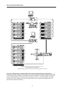
DSP OUT
The DSP output signal – i.e. the post-digital-signal-processing-unit audio signal – is present at the
DSP OUT. The DSP output signal is simultaneously fed to the power amplifier output stage and is
correspondingly amplified present at the power amp’s main outputs.
The DSP OUT can be utilized for feeding the digitally processed audio signal from the RCM-24 Re-
mote Control Module to additional power amplifiers (without DSP-module); e.g. for increasing the
overall output power. With a nominal level of +6dBu and a maximum level of +21dBu (8.7V) the output
signal is electronically balanced. Output impedance is 100
Ω
.
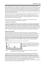
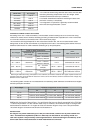
CONTROL PORT
The CONTROL PORT offers two freely programmable control inputs and
control outputs as well as the reference connections for ground potential and
+5V. Using the PC Windows software IRIS, the control inputs can be
configured and serve for instance for Power-On / Stand-by switching, preset
switching or parameter control.
The two control contacts IN1 / IN2 are internally set to +5V (open) via pull-up
resistors. Activating the control inputs is possible by closing the contacts to ground potential (pin 3) via
external switches, pushbuttons or relays.
The two control outputs OUT1 / OUT2 are carried out as Open Collector Outputs. In non-active state
(Off) they provide high ohmic resistance. In the active state (On) these outputs are connected to
ground. The outputs serve for signalling internal operational states. They can be used for the direct
triggering of LEDs, indication lights or relays. The +5V reference connector provides power supply for
externally connected appliances with amperage of maximally 100mA. The control outputs allow signal
indication of operational states (critical temperature, exceeding or decline of defined limit values, faults,
etc.) at central operator desks or to other systems (fire alarm system, general alert system) even with-
out PC. For further detail about configuring the control ports, please refer to the documentation accom-
panying the IRIS software.
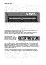
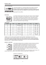
REAR PANEL
The CONTROL PORT offers two freely programmable control inputs and
control outputs as well as the reference connections for ground potential and
+5V. Using the PC Windows software IRIS, the control inputs can be
configured and serve for instance for Power-On / Stand-by switching, preset
switching or parameter control.
The two control contacts IN1 / IN2 are internally set to +5V (open) via pull-up
other hand, this LED lights constantly, reducing the volume is recommended to prevent the loudspeak-