Electro-Voice EVF/EVH User Manual20
4.0 Preparing EVF and EVH Systems for Installation (cont’)
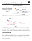
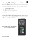
To configure for biamp operation, remove the switch card by drawing it toward you using the central finger
hole. (The switch can also be removed with the end of a flat-blade screwdriver, by placing the blade end
in the switch hole and using the adjacent edge of the input panel as a fulcrum. To facilitate this operation,
there is a small recess in the edge of the input panel adjacent to the hole in switch card.) Reinsert the
switch card in its biamp-operation position (right position in the picture of Figure 11).
4.3 Rotation of High-Frequency Waveguides (EVF systems)
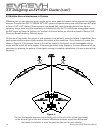
All high-frequency waveguides have their horizontal and vertical patterns molded in for easy identification
of orientation and are rotatable according to the following procedure:
1. With a #2 Phillips screwdriver, remove the four screws on each side of the enclosure and
pop the grille out.
2. With a #2 Phillips screwdriver, remove the 12 screws holding the compression-driver/
waveguide assembly.
3. Rotate the assembly 90° and reinstall.
4. Reinstall the grille.
4.4 Rotation of High-Frequency Waveguides and Mid-Frequency Waveguide Contours (EVH
systems)
1. With a #2 Phillips screwdriver, remove the four screws on each side of the enclosure and
pop the grille out.
2. With a #2 Phillips screwdriver, remove the four screws holding the compression-driver/HF
waveguide assembly.
3. Use a 6-mm Allen (hex) wrench to remove the two rails that hold the HF waveguide
assembly.
4. Use a 4-mm Allen (hex) wrench to remove the four screws holding the hard foam
mid-frequency waveguide contours in place on the left and right sides of the enclosure.
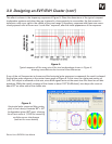
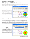
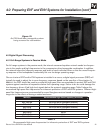
Figure 12 shows a contour in the process of being removed.
5. Rotate and reinstall the contours in the top and bottom of the enclosure.
6. Reinstall the two rails that hold the HF waveguide assembly.
7. Rotate and reinstall the compression-driver/HF waveguide assembly.
8. Reinstall the grille.


