


The DL10X passes AES2-1984/ANSI S4.26-
1984 with the following values:
Z
MIN
= 6.0 ohms at 350 Hz
P
E
(max) = 300 watts
Test voltage = 42.5 volts rms,
95.0 volts peak
(+6 dB)
Selected decade = 50-500 Hz
RESPONSE IN STANDARD BAFFLE
AES requires a large, planar baffle for this test,
WHICH IS INTENDED TO SHOW SMOOTH-
NESS AND OFF-AXIS RESPONSE, NOT
BASS RESPONSE. This has proven to be
inconvenient and prohibitive, due to its size.
Here, we have chosen our lab-standard, low-
diffraction, 12-cubic-foot test enclosure, which
will demonstrate the same characteristics as
the AES standard baffle (see Figure 2). A
smoothed, swept-sine-wave input is used for
this measurement to provide a more informa-
tive curve to the end user.
TYPICAL ENCLOSURES
The most extended bass, lowest distortion and
best control is usually realized in properly de-
signed vented enclosures. In such designs, the
vent, or port, actually provides the lowest oc-
tave of output. The vent is driven to full acoustic
output by a relatively small motion of the speaker
cone itself, acting through the air contained
within the enclosure. The excursion of the DL10X
at these frequencies is much reduced com-
pared to sealed or open-back enclosures, di-
rectly reducing harmonic distortion and the
possibility of speaker bottoming. Used as a
midbass speaker, horn loading may be desir-
able for the DL10X. Usable frequency re-
sponse in a horn-type enclosure can extend
from 100 to 4,000 Hz. Please note, however,
that in a horn-loaded system, the actual perfor-
mance greatly depends on the design of the
horn enclosure. Factors such as flair rate,
mouth size, and rear chamber volume play
critical roles in the performance of any horn-
loaded system.
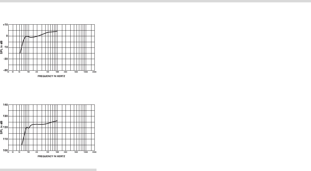
Normally Tuned Enclosures
The DL10X in a 1.0-cubic-foot enclosure tuned
to 75 Hz has essentially flat response to 90 Hz
(See Figure 9).
Figure 11 shows the maximum predicted output
level, taking power handling and displacement
limitations into account.
SUBPASSBAND SPEAKER PROTECTION
Below the enclosure tuning frequency, cone
excursion increases rapidly. Since acoustic
output is also falling rapidly, there is no utility in
driving the system with signals much below
tuning frequency. While such signals may be in
the program material, they are often extrane-
ous, such as a dropped microphone. The
Electro-Voice EX-24, XEQ-2 and XEQ-3 elec-
tronic crossover/equalizers can provide sub-
passband protection. The 3-dB-down points
are 30 Hz (EX-24 and XEQ-2) and 16 Hz or 32
Hz (XEQ-3).
Other high-pass filters are available, and one-
third-octave equalizers can also be effective at
providing the required protection.
MOUNTING
The DL10X may be front- or rear-mounted
and materials available.
Great care was taken in the selection of dia-
phragm materials and construction to ensure
smooth, musical upper-bass reproduction. The
cone has a moisture-repellent treatment, allow-
ing it to be used in harsh and humid conditions.
(Do not expose the cone to direct water or
sunlight.)
The DL10X is a true high-fidelity woofer in every
sense, being capable of high output, low distor-
tion, and solid bass response.
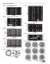
DIRECTIONAL CHARACTERISTICS
The directional characteristics of the DL10X in
a 2.0-cubic-foot vented enclosure were mea-
sured in Electro-Voice’s large anechoic cham-
ber. The test signal was one-third-octave fil-
tered pink noise centered at the frequencies
indicated. A full spherical measurement sys-
tem, which is completely compatible with the
AcoustaCADD
TM
computer-aided design pro-
gram, was used. All directional information was
measured at 20 feet. Figure 8 illustrates the
horizontal and vertical polar responses. Figure 6
shows the horizontal and vertical beamwidths.
Beamwidth is the angle at which the horizontal
and vertical polar responses have decreased in
level by 6 dB when compared to the axial
frequency response. Figure 7 illustrates the
total directivity of the DL10X. The directivity
factor R
θ
(Q) is the relative value, at a point, of
the DL10X when compared to an ideal spheri-
cal response. The directivity index, D
i
, is calcu-
lated by the formula: D
i
= 10 log
10
R
θ
.
TYPICAL AMPLIFIER SIZE
300-600 watts per woofer is the optimal ampli-
fier size. Amplifiers of this size will allow maxi-
mum output with minimal risk of speaker dam-
age when properly used. Smaller amplifiers
can also be used with excellent results—the full
capabilities of the speaker will simply not be
used.
POWER-HANDLING TEST
Electro-Voice components and systems are
manufactured to exacting standards, ensuring
they will hold up, not only through the most
rigorous of power tests, but also through contin-
ued use in arduous, real-life conditions. Two
main test specifications are used: the “AES
Recommended Practice for Specification of
Loudspeaker Components Used in Professional
Audio and Sound Reinforcement” (AES2-1984/
ANSI S4.26-1984) and the “EIA Loudspeaker
Power Rating Full Range” (ANSI/EIA RS-426-A
1980). Both of these specifications use noise
spectrums which mimic typical music and test
the thermal and mechanical capabilities of the
components. Electro-Voice will support relevant
additional standards as and when they become
available. Extreme, in-house power tests, which
push the performance boundaries of the com-
ponents, are also performed and passed to
ensure years of trouble-free service.
Specifically, the DL10X passes ANSI/EIA
RS-426-A 1980 with the following values:
R
SR
= 6.9 ohms (1.15 x R
E
)
P
E
(max) = 300 watts
Test voltage = 45.5 volts rms,
91.0 volts peak
(+6 dB)
_______________________
4. Teflon
®
is a registered trademark of DuPont.
Dimensions (see Figure 10),
Outer Diameter:
266 mm (10.48 in.)
Overall Depth:
120 mm (4.7 in.)
Net Weight:
8.6 kg (19.0 lb)
Shipping Weight:
9.5 kg (21.0 lb)
DESCRIPTION
The DL10X low/mid-frequency reproducer is a
10-inch, 8-ohm driver designed for professional
high-level, high-fidelity monitoring and sound
reinforcement. At the heart of this speaker is a
carefully engineered drive system. Its design
assures linear, low-distortion output, high power
capability and efficient heat transfer.
Incorporated into the design are three exclu-
sive Electro-Voice innovations. PROTEF
TM
coat-
ing (U.S. patent #4,547,632), a Teflon
®
-based
coating, is applied to the inside diameter of the
top plate.
4
Occasional violent power peaks of
several seconds may expand a transducer’s
voice coil into contact with the top plate, caus-
ing failure. PROTEF provides protection against
such failure. The coating lubricates any rubbing
contact and provides electrical insulation be-
tween the coil and the steel top plate. The
Thermo Inductive Ring (TIR
TM
) and Flux De-
modulation Device (FDD
TM
), also included in
the DL10X design, are aluminum castings fas-
tened to the pole of the magnet. They provide a
shorted turn to control inductance and provide
a major heat transfer path from the voice coil,
which improves power handling and reduces
thermal dynamic-range compression.
The voice coil itself is constructed of edge-
wound rectangular aluminum wire, mounted on
a rugged laminated polyimide former. The com-
plete assembly is low in mass and is fabricated
using the most advanced epoxies, insulations
FIGURE 10 — Predicted Low-Frequency
Response in a Typical
Enclosure (1.0 ft
3
tuned to 75 Hz)
FIGURE 11 — Maximum SPL at 1 Meter in a
Typical Enclosure
(1.0 ft
3
tuned to 75 Hz)