


Electro-Voice
®
4
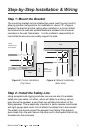
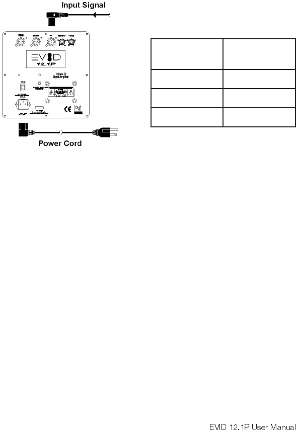
Figure 7: Wiring Configuration
Step 3: Wire the Speaker
A typical wiring configuration is shown in Figure 7. It is highly advisable
to support the unit while these connections are being made. When
mounting the speaker in a corner mount configuration, a right angle XLR
connector such as Neutrik #NC3MRC or equiv. is required for the signal
connections (see Figure 7). Connect the line level signal from the mixer,
pre amplifier or other source into the line input connector. Plug in the
power cord and connect the unit to a standard 120VAC power source.
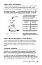
The proper crossover setting is
determined by the satellite
speakers used. The following
are general guidelines:
Adjust the crossover according
to the chart above. Set the
appropriate sub level before
making the final mounting to the
bracket.
Step 4: Mount the Speaker to the Bracket
First remove the two Phillips-head screws on the rear of the enclosure.
Use the supplied eyebolt to mount one mounting clip to the top of the
speaker as shown in Figure 8. Check to make sure that the wiring
connections to the amplifier and the satellite speakers are correct and
secure.
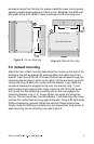
For corner mounting
Attach the four rubber mounting feet to the front side edges, and secure
the safety line to the eyebolt. Lift the enclosure up to the ceiling and
center it back it into the corner until it touches the bracket rungs, then
carefully lower it so the top clip hooks over the top rung of the bracket
(1). Insert one of the 3/8-16-thread Phillips-head screws through the
remaining clip and, with the clip pointing up, thread the screw finger-tight
into the lower mtg. hole on the enclosure (2, 3). Level the clip and tighten
securely with a #3 right-angle Phillips screwdriver. Even though the
etilletaS
rekaepS
revossorC
gnitteS
2.3zH011
2.4zH59
2.6zH08