


PAGE 8
SPECIFICATIONS ARE SUBJECT TO CHANGE WITHOUT NOTICE DMS3040/3080/3120
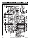
FUNCTION SWITCHES AND JUMPERS
UNDERSTANDING THE INPUT FUNCTIONS
V1
V2
M2
M1
ANY
INPUT
AUDIO OUT
SOURCE IN
DMS Anyinput
VOX SEND
MUTE RECEIVE
TO VOX BUSS 1
TO VOX BUSS 2
FROM MUTE BUSS 1
FROM MUTE BUSS 2
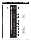
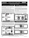
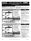
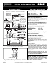
DUAL VOX AND DUAL MUTE - The Amplifier provides two inde-
pendent VOX (V1 & V2) and two MUTE (M1 & M2) SYSTEMS
FUNCTION SOCKETS - EACH INPUT IS PROVIDED WITH A
VOX (V1 & V2) AND A MUTE (M1 & M2) SOCKET.
INPUTS VOX AND MUTE FUNCTION - All Inputs including the
Module provide 2 - VOX SEND and 2 MUTE RECEIVE functions.
The VOX and MUTE functions are SWITCHED-ON, on each Input,
by Internal Jumpers provided for each Input. Two VOX BUSS
SEND (V1 & V2) and two MUTE BUSS RECEIVE (M1 & M2) can
be independently or simultaneously SWITCHED-ON to suit the
application requirement.
Fig. 8 - Any Input VOX and MUTE Functions
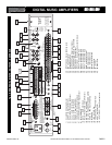
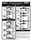
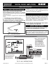
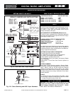
JUMPER SETTINGS - The VOX and MUTE Functions are
SWITCHED-ON or OFF by setting the JUMPERS on the VOX (A)
and MUTE (B) SOCKET. See Fig. 8A.
The SOCKETS are located on the Main PCB inside the Amplifier
as shown on the SWITCHES and JUMPERS LOCATION DIA-
GRAM in this Manual. Each Socket is identified by an ID NUMBER
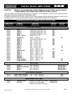
and the FUNCTION and DEFAULT settings are listed on the
FUNCTION SWITCHES and JUMPERS DEFAULT SETTING
TABLE in this Manual.
TO SET: Lift the Jumper and reset as required. making sure that
the JUMPER is properly positioned over the two shorting pins.
The VOX JUMPER has three positions: OFF, V1 and V2
The MUTE JUMPER has three positions: OFF, M1 and M2
V1
V2
OFF
VOX 2 BUSS OFF
M2
M1
OFF
X
MUTE 2 BUSS ON
X
MUTE 1 BUSS OFF
AUDIO OUT
DMS Anyinput 02
VOX SEND
MUTE RECEIVE
SW215
SW220
JUMPER
ANY
INPUT
SOURCE IN
JUMPER
JUMPER
VOX 2 BUSS ON
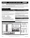
Fig. 8B - Any Input VOX 1 and MUTE 2 Activated
JUMPER
OFF
SW215
V 1
V 2
OFF
SW220
M 1
M 2
AB
JUMPER JUMPER
Vox Mute Socket
VOX JUMPERS
SOCKET
MUTE JUMPERS
SOCKET
SOCKET
ID NO.
The figure below shows how the VOX 1 Logic Switch and the
MUTE 2 Logic Switch are SWITCHED-ON by moving the Jumpers
from the OFF position to the V 1 and M 2 position. When the Input
is activated by a Source signal the corresponding VOX Signal is
sent to the V1 BUSS. When the VOX 2 is activated by another Input
the MUTE Signal is present on the MUTE 2 BUSS and it will
MUTE this Input
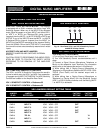
SETTING THE VOX AND MUTE JUMPERS
Fig. 8A - VOX and MUTE Sockets
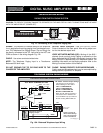
More than one JUMPER may be used on a VOX SOCKET as
shown below. In this example both the VOX 1 and VOX 2 functions
are SWITCHED -ON when the Input is activated. For this purpose
additional JUMPERS are packed with each Amplifier.
OFF
V 1
V 2
A
JUMPER
Vox Socket 01
VOX SOCKET
JUMPER
VOX 1 BUSS ON
VOX 2 BUSS ON
SETTING MORE THAN ONE FUNCTION
More than one JUMPER may be used on a MUTE SOCKET as
shown below. In this example both the MUTE 1 and MUTE 2 func-
tions will MUTE this INPUT when either VOX 1 or VOX 2 are acti-
vated by other INPUTS.
OFF
M 1
M 2
B
JUMPER
Mute Socket 01
MUTE SOCKET
JUMPER
MUTE 1 BUSS ON
MUTE 2 BUSS ON
NOTE: BE SURE NOT TO SET BOTH THE VOX AND CORRE-
SPONDING MUTE ON THE SAME INPUT OR THE INPUT WILL
MUTE ITSELF WHEN ACTIVATED.
EXAMPLE: INPUT 1 - V 1 and M 1 BOTH ON.
PROFESSIONAL AUDIO & SOUND
®
TM
DIGITAL MUSIC SERIES
DIGITAL MUSIC AMPLIFIERS