


SPECIFICATIONS MK8126
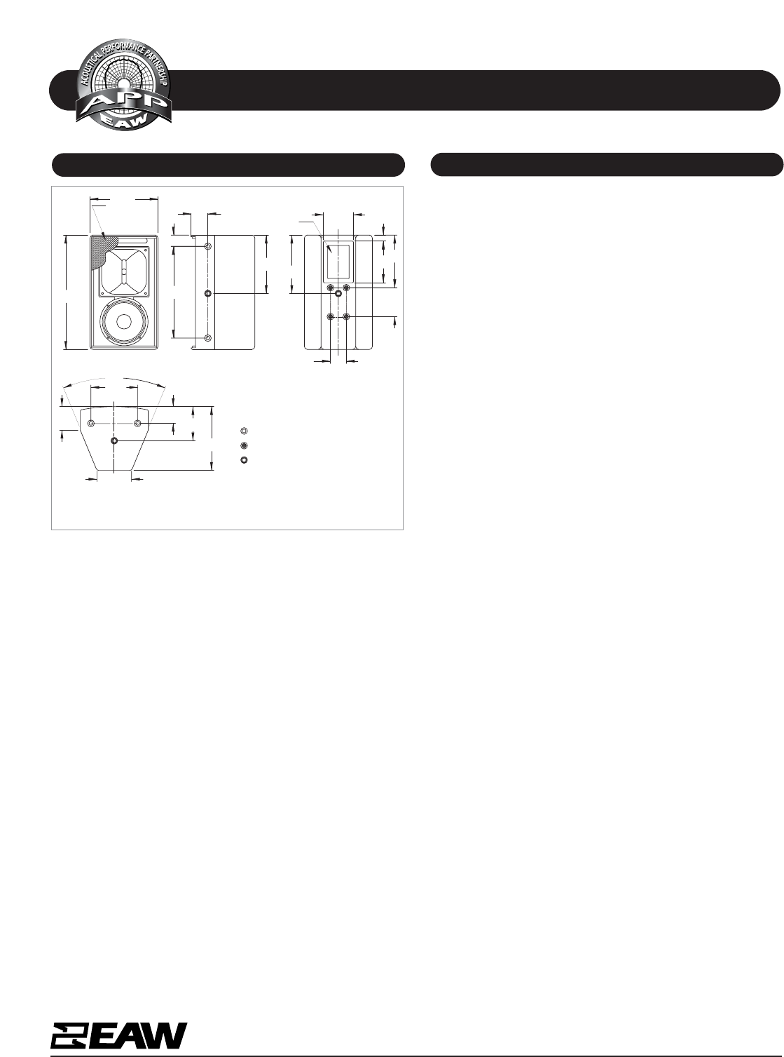
DIMENSIONAL DRAWING
A & E SPECIFICATIONS
One Main Street, Whitinsville, MA 01588 508 234 6158 Toll Free 800 992 5013 FAX 508 234 8251 info@eaw.com www.eaw.com
EAW products are continually improved. All specifications are therefore subject to change without notice. MK8126/0004843/001/2 pp September 2002 Printed in USA
The two-way full range loudspeaker systems shall incorporate
an 8-in LF transducers and a 1-in exit/1.5-in voice coil com-
pression driver HF transducer.
The LF drivers shall be mounted in an optimally vented enclo-
sure tuned for maximum low frequency response. The HF driv-
er shall be loaded on a constant directivity horn with a nom-
inal coverage pattern of 120° (h) x 60° (v). The HF horn shall
feature a square flange allowing it to be rotated 90°. An
internal passive filter network shall provide fourth order
acoustical crossover and system equalization between the low
and high frequency sections.
System frequency response shall vary no more than ±3 dB
from 89 Hz to 18 kHz measured on axis. The system shall pro-
duce a Sound Pressure Level (SPL) of 95 dB SPL on axis at 1
meter with a power input of 1 Watt, and shall be capable of
producing a peak output of 125.8 dB SPL on axis at 1 meter.
The system shall handle 300 Watts of amplifier power (AES
Standard) and shall have a nominal impedance of 8 Ohms.
The loudspeaker enclosure shall be trapezoidal in shape. It
shall be constructed of exterior grade Baltic birch plywood
and shall employ extensive internal bracing. It shall be fin-
ished in wear resistant textured black paint. Input connectors
shall be two-terminal barrier strip. A total of 13x 3/8"-16
threaded mounting/suspension points (3 each top and bot-
tom, 3 per side and 1 back) shall be provided. Four addition-
al mounting points shall be provided on the rear configured
to accept an Omnimount brand Series 100 bracket. The front
of the loudspeaker shall be covered with a powder coated per-
forated steel grille.
The 2-way full range loudspeaker shall be the EAW model
MK8126.
7.25
5.00
C
INPUT
9.09
10.21
.97
5.25
L
509180 (1) 9/17/02
BACK
NOTES
1. SYMBOL INDICATES MOUNTING POINT,
3/8-16 THREADED HOLE (PI ANGLE).
2. SYMBOL INDICATES MOUNTING POINT,
5/16-18 THREADED HOLE (OMNI MOUNT).
3. SYMBOL INDICATES MOUNTING POINT,
3/8-16 THREADED HOLE (RIVNUT).
19.75
(1.95)
2.90
PARTIALLY
SHOWN
GRILLE
11.75
5.90
11.03
15.85
(6.00)
C
4.08
L
8.07
FRONT
2.75
DIMENSIONS APPLY TO
TOP AND BOTTOM
BOTTOM
45°
2.90
DIMENSIONS APPLY
TO BOTH SIDES
RIGHT SIDE
10.09
Manufacturing tolerances are +/- 0.13 and +/- 1°