SPECIFICATIONS KF755F
DESCRIPTION
PERFORMANCE
APPLICATION
One Main Street, Whitinsville, MA 01588 508 234 6158 Toll Free 800 992 5013 FAX 508 234 8251 info@eaw.com www.eaw.com
EAW products are continually improved. All specifications are therefore subject to change without notice. KF755F/2 pp October 2001 Printed in USA
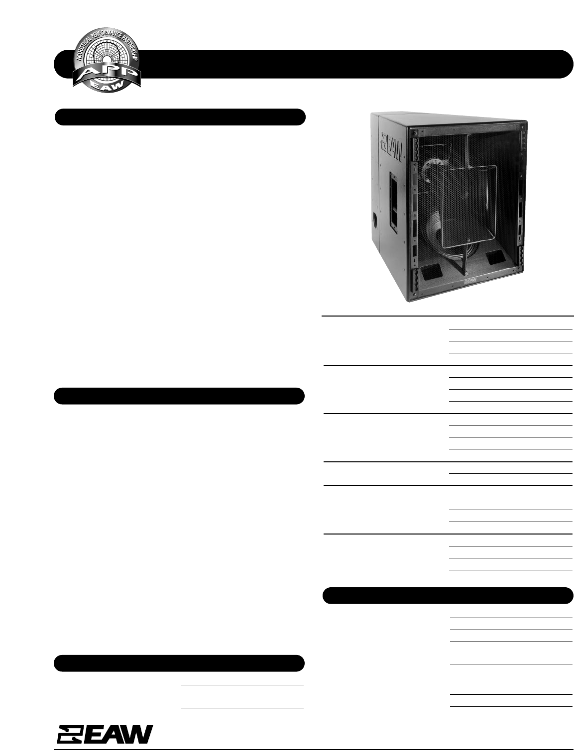
The KF755F 3-way tri-amplified full range system is the down-
fill companion to the KF750F array module.
Since the large mid frequency horn contains both the high
and
low frequency subsystems, the overall package is just 31-in
high. Still, the KF755F provides consistent wideband pattern
control in both the vertical and horizontal planes.
The large MF horn loads a specially designed 10-in midrange
cone whose geometry exactly matches the rear of its phase
plug assembly. By developing the driver and phase plug as a
single unit, pathlength discontinuities within the MF pass-
band have been eliminated without compromising the direc-
tional qualities of the source as all previous phase plug
designs have.
The 2-in exit/4-in voice coil HF compression driver is mounted
on an asymmetrical 35° x 35° constant directivity horn
mounted coaxially within the MF horn flare. Vertical coverage
is 0° to -35°.
The KF755F’s 15°-per-side trapezoidal enclosure features
eight 4-position flytracks (four each front and rear) that
accept industry-standard flyclips.
The KF755F provides optimized downfill coverage below flown
arrays or, when inverted, provides upfill balcony coverage
from ground-stacked arrays when flying arrays are either not
allowed or not desired.
At just 31-in tall and under 200 pounds per module, KF700
Series arrays are smaller, lighter, more efficient and, therefore,
more powerful than those built with other systems. These
smaller, lighter arrays are easier to fly, require less truck space
and permit more open sight lines to cover any given venue.
The KF750F works with a companion downfill module, the
KF755F to provide full range nearfield coverage below the
array. The KF755F’s smooth power response produces remark-
ably even SPL levels throughout the coverage area, allowing
it to be used as a stand-alone system when necessary in
applications demanding that coverage pattern.
Applications include:
Concert Tours Performing Arts Centers
Houses or Worship Theaters
Axial Sensitivity (dB SPL, 1 Watt @ 1m)
LF 99
MF 108
HF 115
Impedance (Ohms)
LF 8
MF 8
HF 8
Power Handling, (Watts Continuous)
LF 600
MF 400
HF 200
Recommended High-Pass Filter
24 dB/Octave 30 Hz
Calculated Maximum Output (dB SPL @ 1m)
LF Peak/Long Term 132/126
MF Peak/Long Term 140/134
HF Peak/Long Term 144/138
Nominal Coverage Angles, -6 dB points (degrees)
Horizontal 35
Vertical 35 (0 to -35)
PHYSICAL
Configuration 3-way, full range
Powering Tri-amplified
LF Subsystem 12-in cone, vented
MF Subsystem 10-in cone, Radial Phase Plug™
asymmetrically horn-loaded
HF Subsystem 2-in Exit/4-in voice coil
compression driver on
asymmetrical high Q horn
Coverage Angles 35° (h) x 35° (v, 0° to -35°)
Frequency Response (Hz)
±3 dB 48 Hz to 18 kHz
-10 dB 30 Hz


