


CAZ Series – 5
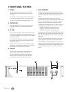
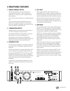
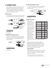
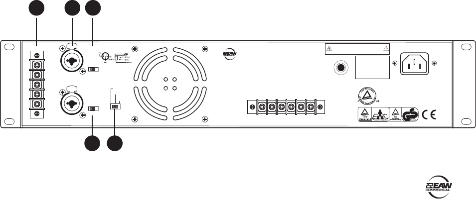
4. REAR PANEL FEATURES
1. SCREW TERMINAL INPUTS
The CAZ series amplifi ers give you three options for
connecting the input signal — these screw terminals,
and XLR or 1/4” connectors via the "combination" input
described below.
You can connect either a balanced or an unbalanced signal
here.
The screw terminal and the combination inputs are in
parallel, and are identical electrically. Since these two
inputs are in parallel, you shouldn’t connect more than one
source to the INPUT A or INPUT B jacks.
2. COMBINATION INPUTS
These inputs allow you to connect balanced XLR plugs or
1/4" TRS or TS plugs from line-level sources.
Use balanced connections where possible, as these offer
better rejection of noise than unbalanced lines.
Use high-quality, three-conductor shielded cable for
balanced connections. The better the shield, the better the
audio signal is protected from induced EMI and RFI.
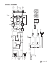
3. SUBSONIC FILTER
Turn this switch on to engage a low-frequency cutoff (high-
pass) fi lter at 30 Hz. The frequency range below 30 Hz is
attenuated.
The CAZ series amplifi ers can amplify signals below 20 Hz,
but most speakers can’t reproduce frequencies that low.
By engaging the SUBSONIC FILTER, you allow the amplifi er
to power only the frequencies you can hear. In addition,
this fi lter can reduce low-frequency stage noise (footsteps)
and accidental microphone pops that could damage a
loudspeaker.
Leave this off if you are powering a subwoofer, or if your
speakers can reproduce low frequencies such as the kick
drum range.
4. CLIP LIMIT
When engaged, the CLIP LIMIT switch protects your
loudspeakers from the effects of clipping. It is designed to
be virtually transparent, meaning you probably won’t even
notice any audible difference when the switch is turned on.
We recommend that you leave this switch on at all times.
However, if you are working at quiet levels, or you have
already placed a compressor/limiter in the signal path, you
can leave the CLIP LIMIT switch off.
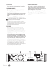
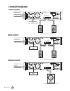
5. AMP MODE
This switch determines the input signal routing within the
amplifi er. For most applications, you will use the STEREO
setting. However, some applications might be better suited
for using either the MONO or the BRIDGE setting.
STEREO: This is the normal position used when amplifying
stereo signals. This mode accepts separate left and right
inputs (A and B), and routes them to the CHANNEL A
and CHANNEL B outputs. Each channel’s Level control
adjusts the gain for its own channel, and each channel is
independent.
MONO: This mode is used when you want to send a mono
signal to both outputs. It accepts a single input (INPUT
A), and routes it to both the CHANNEL A and CHANNEL B
outputs. Each channel’s Level control adjusts the gain for
its own channel.
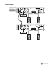
BRIDGE: This mode accepts a single input (INPUT A), and
uses both amplifi er outputs to double the power to one
speaker. Use the Channel A Level control to adjust the gain
(turn the Channel B Level control all the way down). The
hookup diagrams show how to connect a speaker in Bridge
mode.
BREAKER
CLIP LIMIT
ON
OFF
STEREO
SUBSONIC
FILTER AT 30Hz
ON
OFF
PUSH
PUSH
AMP MODE
MONO
BRIDGE
CAUTION
TO REDUCE THE RISK OF FIRE OR ELECTRIC SHOCK,
DO NOT EXPOSE THIS APPARATUS TO RAIN OR
MOISTURE. SEE INSTRUCTIONS BEFORE USING.
INPUT
B
LINE
(BALANCED)
B (+)
B (+) B (-)
CHANNEL B BRIDGED CHANNEL A
(+) (-) A (+) A (-)
B (--)
GND
A (--)
A (+)
INPUT
A
LINE
(BALANCED)
SERIAL / DATE CODE
INPUT
CONNECTION
MANUFACTURED IN
CHINA
2004 LOUD TECHNOLOGIES INC.
"EAW" IS A REGISTERED TRADEMARK
OF LOUD TECHNOLOGIES INC.
CAZ2500-AMPLIFIER
2 3
4 5
1