


Eastern Acoustic Works One Main Street Whitinsville, MA01588 tel 800 992 5013 / 508 234 6158 fax 508 234 8251 www.eaw.com
EAW products are continually improved. All specifications are therefore subject to change without notice. Part Number: RD0188 (C) AX364 November 2005
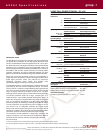
AX364 Specifications group · I
AX SERIES TECHNOLOGY
CONVENTIONALLOUDSPEAKERS
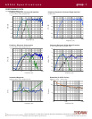
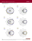
Good arrayability depends on the beamwidth patterns as well as the off-axis response to be symmetrical for both the
horizontal and vertical planes. A typical, high power, loudspeaker baffle is shown in Fig 1. For this and similar
arrangements, the height or width of each horn is typically smaller than ideal, reducing pattern control at the low end of
their passbands in one plane. Because the driver arrangement is asymmetrical, the projection pattern will be
asymmetrical left-to-right and up-to-down. In addition, the physical spacing between drivers means the time arrival from
each driver changes with listener location. While signal delays can correct for time arrival differences, the optimum delays
can only be set for one direction. Listeners off-axis of this path will still experience different arrival times from the various
drivers. When multiple loudspeaker are arrayed, these problems are compounded by the drivers in the additional
loudspeakers. Better layouts, such as found in EAW’s KF730, KF600, KF750, KF760, and KF850 Series have improved
on some of these issues, but not all of them at one time.
To eliminate arrival time differences, provide smooth off-axis response, and optimize pattern control for arraying, drivers
must be positioned symmetrically with as little physical offset as possible in all three planes . Additionally, horns need to
be symmetrically sized and as large as possible to achieve the desired pattern control at their lowest frequencies.
COAXIALDRIVERS
Asolution for the above problems is the co-axial driver, where two passbands, typically an LF (low frequency) or MF (mid
frequency) cone driver and HF (high frequency) compression driver are combined within a single driver assembly. Apassage
is created in the center, i.e. the pole piece, of the cone driver through which the HF driver's energy passes . While this can
almost eliminate any time arrival differences from the drivers, there are significant limitations to typical co-axial designs.
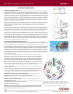
Horn-loading is normally required for high output loudspeakers. To this end, the cone driver’s diaphragm is used as the
HF horn. However, this allows the HF to be modulated by high cone excursions. In addition, a horn’s rate of expansion
(curvature angle) should always increase towards the horn mouth. Simply loading a coaxial driver onto a horn breaks this
rule by creating a decrease in expansion rate at the driver-to-horn throat junction as shown in Fig 2. This causes
significant reflections off the horn walls, with resulting multiple arrivals at the listener, and prominent, undesirable side
lobes. Also, the path length from the cone center to the horn throat is longer than that from the circumference. In the
crossover region, this difference is typically an appreciable fraction of a wavelength. All these things result in uneven
frequency response, smeared transients, and poor pattern control.
(CSA) CONCENTRIC SUMMATION ARRAYTECHNOLOGY
To solve these problems, EAW Engineers developed a new, sealed, coaxial driver. Its MF cone and HF compression
drivers share a single magnet structure, bringing the MF and HF sources as close together as physically possible. This
produces an Acoustic Singularity, essentially a point source, over the MF/HF operating range of 275 Hz to 20 kHz.
The real challenge was coupling this MF/HF device to a single horn without the acoustical difficulties of typical coaxial
drivers. This required creating both an always-increasing horn expansion rate over the HF range (Fig 3) and a phase plug
to properly load the MF cone driver, both to improve its efficiency and eliminate cone-to-horn path length differences. The
solution involved a modified version of EAW's patented Radial Phase Plug design, developed especially for cone drivers.
The phase plug was modified both to accommodate the AX's smaller MF driver diaphragm and to allow a conical HF
waveguide to nest within its center, optimized for proper HF wavefront expansion into the horn (Fig 4). While a physically
elegant solution, the waveguide's location within the MF phase plug meant it had to be acoustically transparent to MF
energy and opaque to HF energy.
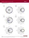
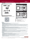
Green circle: circum = 8.017, open = [(2 x 0.386) + (2 x 0.415)] / 8.017 = 20%
Red circle: circum = 11.728, open = [(2 x 0.315) + ( 2 x 0.822)] /11.728 = 20 %
Blue circle: circum = 14.313, open = [(2 x 0.424) + ( 2 x 1.007)] / 14.313 = 20 %
0.386
0.415
0.315
0.822
0.424
1.007
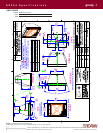
Fig 1 - Conventional High Output Loudspeaker
Fig 2 - Typical Coax HF Expansion
Fig 4 - AX Coaxial Driver
Fig 3 - AX Coax HF Expansion
Fig 6 - AX HF Waveguide Open Area at 3 Cross-sections
Aseries of holes was added to the waveguide that met both acoustical criteria. The location and sizing of
these holes was based on a numerical sequence called The Fibonacci Numbers, first identified by
mathematician Leonardo Fibonacci. The holes were laid out along the walls of the waveguide by
crisscrossing spirals based on the sequence. The holes allow the waveguide to act as two mechanical
filters: a low pass for the MF and a high pass for the HF. This behavior was used to refine the hole shapes,
sizes, and quantities, the goal being raw MF and HF responses that could be easily smoothed by simple
passive filters and digital signal processing (DSP). The open area of the waveguide was evenly
distributed along the walls to achieve symmetrical off-axis MF response. At the same time, the hole
shapes and sizes were randomized to randomize the minor HF nulls caused by the holes. This resulted
in any cross section through the waveguide being physically 20% open and 80% solid (Fig 5).
AX SERIES APPLICATION
To give array designers the most flexible, predictable and accurate array modules ever, this patent-
pending, CSAdevice was coupled to a selection of high-Q and medium-Q horns. Closely coupled, dual
12-inch woofers located on opposite edges of the horn extends the Acoustical Singularity concept into
the low frequencies. Both the MF/HF horns and dual-trapezoidal enclosures are symmetrical. This
means that both the horns and enclosures are fully rotatable to create the desired array pattern.
EAW patents for the fundamental ideas behind the AX Series:
1996 US Patent 6,118,883 LF spacing to match beamwidth through crossover within a horn:
The goal: Consistent power response across LF to MF sub-system transitions.
The solution:Aprecise formula to calculate the LF driver spacing required by a given MF horn mouth size.
1996 US Patent 6,094,495 Radial Phase Plug:
The goal: a midrange driver that could couple to a horn without multiple path lengths, multiple arrivals, or
frequency response anomalies.
The solution:Acone driver with a small-radius dust cap coupled to a Radial Phase Plug that equalizes
path lengths from the entire driver surface to the horn throat.
2004 Patent Pending CSATechnology:
The goal: a coaxial MF/HF driver that could function as an Acoustical Singularity when coupled to a horn.
The solution: A new sealed MF/HF driver, whose cone and compression elements share the same
magnet structure, and a new phase plug with an HF waveguide that allows MF energy to pass through
while properly guiding the expansion of the HF wavefront.