


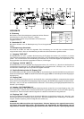
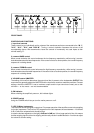
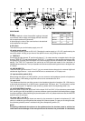
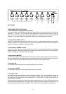

REAR PANEL
8. fuse
In cases of defects or when the amplifier is going to be used
on a different mains voltage, exchanging the fuse should be
left to experienced service personnel.
A label stating the value of the new fuse has to be attached
to the appliance’s rear panel.
9. DC switch
This switch lets you turn the battery supply on or off.
10. mains supply switch
The amplifier is factory preset to 230 V AC. Changing the mains supply to 115 V AC is performed by the
use of this switch. In doing so you have to first open the cover, using a fitting screw driver.
11. TAPE OUT
Connecting the right channel “R” and the left channel “L” of a tape recorder or cassette deck to the right
channel TAPE OUT “R” and the left channel TAPE OUT “L” connectors on the amplifier provides you with
the opportunity to record the mixed signal of the sound sources that are connected to the amplifier and
playing. The TAPE OUT connectors are carried out as RCA-jacks and meant for the connection of
unbalanced sound sources. The input impedance of the connected recording device has to be higher than
4.7 kohms.
12. AUX IN (INPUT 5)
These two RCA-type connectors “R” and “L” let you connect the two channels of an external high-level
unbalanced signal source — such as an AM/FM tuner, a cassette deck, a CD-player, etc..
13. input sensitivity switch (IN 4)
When setting this switch to its “MIC”-position, you can connect a low-impedance dynamic microphone to
the IN 4, while in LINE-setting a high-level source can be connected to the IN 4.
14. input “IN 4"
This unbalanced input lets you either connect a low-impedance dynamic microphone (30 - 600 ohms) or
a high-level sound source (e. g. AM/FM tuner, cassette deck, CD-player, etc.). The connector is carried
out as 1/4" phone jack. To adjust the input sensitivity, please use the corresponding switch (13).
15. XLR PHANTOM 24 V switch
When this switch is set to ON, pins 2 and 3 of the inputs “IN 2" and ”IN 3" (16) are phantom-powered with
24 V, providing you with the possibility to connect condenser type microphones that need phantom voltage
for proper operation. When switching the phantom power on or off, please make sure that the MASTER
control is set to its minimum.
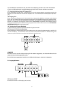
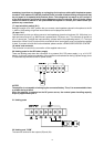
16. inputs “IN 2" and ”IN 3"
These two balanced XLR-type inputs are meant for the connection of dynamic microphones (30 - 600
ohms) or condenser type microphones that accept 24 V phantom power. In case you are using the latter,
the necessary phantom power is activated using the corresponding switch (15).
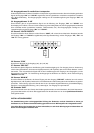
NOTE
Connecting unbalanced microphones to the appliance when the phantom power is switched on
could lead to severe damage on the microphones and is therefore not permissible. It is absolutely
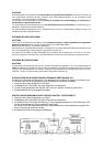
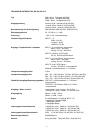
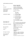
ADMISSIBLE VALUES (FUSE)
230V 115V
MV 512 2,5A 5A
MV 506 1,6A 3,15A
MV 503 1A 2A
12