


DIGITAL SYSTEM AMPLIFIER
12 Owner‘s Manual
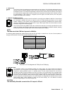
not affected by VLD. Power amplifier channels behave as described in chapter 2.7. The use of VLD considerably expands the
adaptability of a power amplifier. Table 2.4 lists some application examples of VLD.
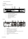
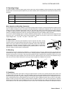
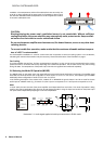
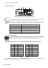
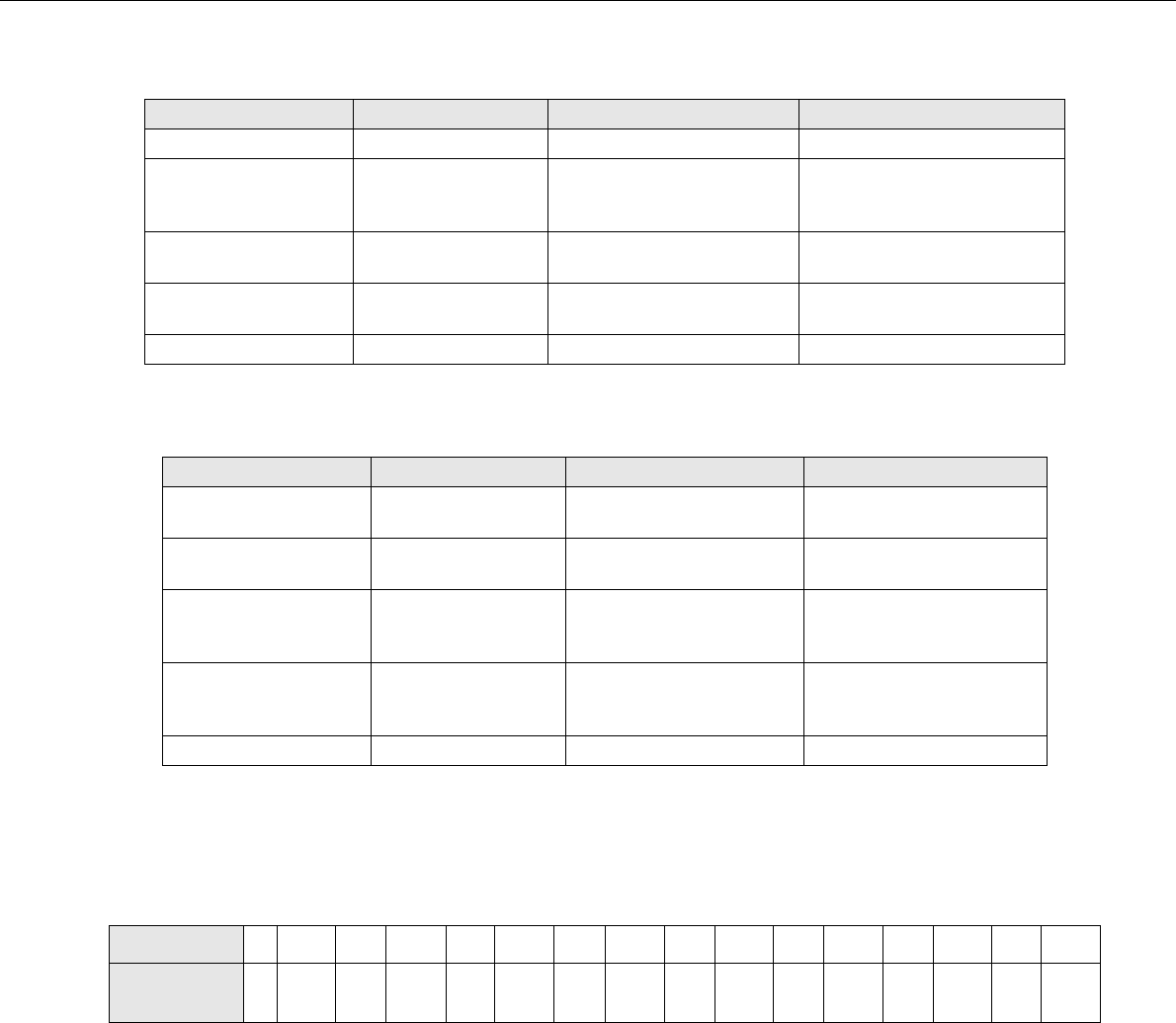
2.9 Power on delay
The ON DELAY switch on the amplifier rear panel allows selection of the power on delay time. Following table shows possible
switch settings and corresponding delay times in seconds.
2 Ω 4 Ω 8 Ω
125 W 2 Ω Mode DSA 8x05
250 W 2 Ω Mode DSA 8x05
4 Ω Mode DSA 8x05
or
2 Ω Mode DSA 8410
500 W 2 Ω Mode DSA 8x05
4 Ω Mode DSA 8x05 or
2 Ω Mode DSA 8410
4 Ω Mode DSA 8410 or
Bridge 2 Ω DSA 8x05
1000 W 2 Ω Mode DSA 8410
4 Ω Mode DSA 8410 or
Bridge 2 Ω DSA 8x05
Bridge 4 Ω DSA 8x05 or
Bridge 2 Ω DSA 8410
2000 W Bridge 2 Ω DSA 8410 Bridge 4 Ω DSA 8410
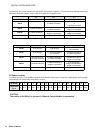
Table 2.3: Maximum Output Power (VLD deactivated)
2 Ω 4 Ω 8 Ω
125 W VLD, all types VLD, all types
2 Ω Mode DSA 8x05 or
VLD DSA 8410
250 W VLD, all types
2 Ω Mode DSA 8x05 or
VLD DSA 8410
4 Ω Mode DSA 8x05 or
2 Ω Mode DSA 8410
500 W
VLD DSA 8410 or
2 Ω Mode DSA 8x05
4 Ω Mode DSA 8x05 or
2 Ω Mode DSA 8410
VLD DSA 8x05 or
4 Ω Mode DSA 8410 or
Bridge 2 Ω DSA 8x05
1000 W 2 Ω Mode DSA 8410
4 Ω Mode DSA 8410 or
Bridge 2 Ω DSA 8x05
VLD DSA 8410 or
Bridge 4 Ω DSA 8x05 or
Bridge 2 Ω DSA 8410
2000 W Bridge 2 Ω DSA 8410 Bridge 4 Ω DSA 8410
Table 2.4: Maximum Output Power (VLD activated)
ON DELAY0123456789ABCDEF
Delay time
(in s)
0 0.15 0.3 0.45 0.6 0.75 0.9 1.05 1.2 1.35 1.5 1.65 1.8 1.95 2.1 2.25
CAUTION:
The setting of ON DELAY is ignored if a Remote Control Module is assembled.