


19
GROUNDED
UNGROUNDED
CHASSIS SWITCH
CIRCUIT TO
T
OUTPUT WIRING MUST BE CLASS 1
BRIDGED
NORMAL
BRIDGED MODE
DUAL
PARALLEL
INPUT
LEVEL LEVEL
CAUTION:
FOR CONTINUED PROTECTION AGAINST RISK OF FIRE
REPLACE WITH SAME TYPE AND VALUE FUSE INDICATED.
REMPLACER PAR U
N FUSIBLE DE MEME TYPE
ATTENTION:
COMME INDIQUE.
230V 50-60 Hz
870 WATTS
ROUTING
0 dB
-9
-16
-30
-1
-4
-2
-3
-5
-6
-12
0 d
B
-9
-30
-1
-4
-2
-3
-5
-6
-12
-16
CHANNELA
INPUTS
CHANNEL
B
INPUTS
70
100
0
100
700
+
+
25V
100V
+
70V
+
+
ISOLATED OUTPUTS
DIRECT OUTPUTS
BRIDGED
1200W/8
600W
+
LOW IMPEDANCE
AUDIO TRANSFORMER OUTPUTS
100V
+
25V
+
70V
+
B A
4
DUALB
A
+
+
T10A/L/250V
MAINS FUSE
DPA 4260
121715
WARNING: TO REDUCE THE RISK OF FIRE
APPLIANCE TO RAIN OR MOISTURE.
AVIS: RISQUE DE CHOC ELECTRIQUE. NE PAS OUVRIR.
NO USER SERVICEABLE PARTS INSIDE. REFER SERVICING TO QUALIFIED SERVICE PERSONNEL.
OR ELECTRIC SHOCK, DO NOT EXPOSE THIS
RISK OF ELECTRIC SHOCK
DO NOT OPEN
CAUTION
POWER
MADE IN GERMANY
+24V ON
0V OFF
+
POWER REMOTE
SEE OPERATING MANUAL!
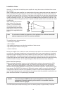
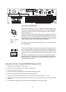
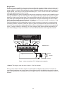
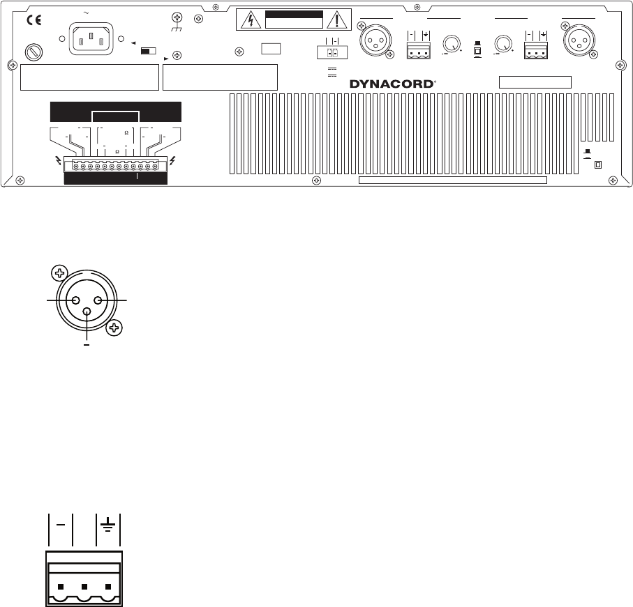
Inputs INPUT CHANNEL A&B
With an input sensitivity of 775 mV = 0 dBu and an input impedance of
20 k ohms, the electronically balanced inputs – INPUT CHANNEL A&B
– are meant for the connection of control ampliers, audio controllers,
mixing consoles, etc.
Peripheral pieces of audio equipment are either connected via the XLR-
type input connectors or using the parallel-linked binding posts. For the
latter option you can utilize the supplied screw-plugs. Thus, carrying the
audio signals through to feed additional power ampliers can be conve-
niently achieved without the need for special split-cables.
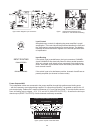
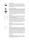
The XLR-type input connectors’ pin-assignment is in accordance to the
IEC 268 standard:
In case the controlling device does not supply balanced output connec-
tors, it is also possible to congure the connectors for unbalanced ope-
ration. Therefore, the common ground (pin 1) has to be connected to the
(–) input (pin 3). The audio signal is now solely fed through the (+) input
(pin 2).
So, to be able to entirely make use of all the advantages the electroni-
cally balanced input stage offers – like the suppression of humming and
interference noise – it is benecial to re-establish balanced input con-
nection whenever possible.
--
+
S
+
PIN 1: SHIELD
PIN 2: a, +
PIN 3: b, -
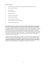
Instructions On How To Install NRS 90208 Extension Kits
• unplug the power amplier from the mains
• detach all screws holding the cover plate of the appliance
• lift and remove the cover plate
• disconnect the at-wire cable of the printed board assembly 81340/1
• detach all screws holding the printed board assembly 81340/1
• remove the printed board assembly 81340/1 and unsolder the resistors R106 … R109
• attach insulators to the input transformers according to the corespondent marks on the printed board
assembly
• re-assemble the appliance by performing all steps described in the opposite order