


Motor Disassembly:
1. Disconnect the tool from the air supply.
2. Invert the tool and place the 57092 Repair Collar around the 02099 Housing and the 51361 Shroud, above the two handle
bosses so that the back-up pad is facing up.
3. Use the 50679 Wrench (26mm) to remove the back-up pad.
4. Insert the 56058 Lock Ring Wrench into the tabs of the 59058 Lock Ring and loosen the lock ring from the 02099 Housing by
turning it counterclockwise.
5. Remove the 51361 Shroud from the 02099 Housing by turning it counterclockwise.
6. Pull the motor assembly out of the 02099 Housing and remove the 58357 Cylinder Seal.
7. Use retaining ring pliers to remove the 95626 Retaining Ring.
8. Fasten the 96346 Bearing Separator between the 51367 Bearing Plate and the 58358 Cylinder Assembly.
9. Place the motor assembly with the bearing separator attached, on the table of the 96232 Arbor Press (#2) so that the counter
balance is pointing toward the floor.
10. Use a 3/16" dia. flat end drive punch as a press tool and push the 57422 Motor Shaft Balancer out of the 01206 Bearing.
11. Remove the rotor, vanes, and the 56047 Key from the motor shaft balancer.
12. Remove the 51366 Bearing Plate from the 57088 Bearing.
13. Fasten the bearing separator between the counter balance and the 57088 Bearing and use the arbor press to
remove the bearing.
14. Secure the counter balance portion of the 57422 Motor Shaft Balancer in a vise with aluminum or bronze jaws so that the
26mm hex end of the 57069 Balancer Shaft is accessible and pointing up.
15. Use a small thin screwdriver to pick the notched end of the 95630 Snap Ring out of the motor shaft balancer. Work the
screwdriver under and around the 95630 Snap Ring.
16. Fasten the bearing separator between the 26mm hex end of the 57069 Balancer Shaft and the 95628 Bearing Shield. Place
the separator on the table of the arbor press so that the hex end of the balancer shaft is pointing toward the floor. Use a 5/16"
dia. flat end punch as a press tool and press the 57069 Balancer Shaft out of the 56052 Bearing.
Motor Disassembly Complete.
Valve Disassembly:
1. Place the 52296 Repair Collar around the 57319 Housing and secure it in a vise so that the air inlet is pointing up.
2. Use two wrenches when removing the air fitting. Place one wrench on the 94523 Inlet Adapter to hold it stationary and use
another wrench to remove the air fitting.
3. Remove the inlet adapter from the valve housing. Note: Refer to the exploded view of the muffler assembly to identify the
parts and their order of assembly.
4. Use needle nose pliers to remove the 01468 Spring and the 01472 Tip Valve. The 01464 Seal can be removed from the
valve housing with a small screwdriver.
5. Use retaining ring pliers to remove the 95558 Retaining Ring and push the 01469 Speed Regulator Assembly along with the
01449 Valve Stem out of the valve housing.
6. Use a 2.5mm dia. drive punch to remove the 12132 Pin and the throttle lever.
Valve Disassembly Complete.
Valve Assembly:
Important: Clean and inspect all parts before assembling.
1. Place the 52296 Repair Collar around the 57319 Housing and secure it in a vise so that the air inlet is pointing up.
2. Install the 01469 Speed Regulator Assembly (includes o-rings) into the valve housing and secure it in place with the
95558 Retaining Ring.
3. Insert the 01449 Valve Stem so that the end with the hole fits into the 01469 Speed Regulator Assembly.
4. Install the 01464 Seal into the inlet so that it is laying flat.
5. Use a needle nose pliers to grasp the white nylon portion of the 01472 Tip Valve and insert the metal pin of the tip valve into
the hole of the 01449 Valve Stem.
6. Install the 01468 Spring so that the smaller end of the spring fits against the center of the tip valve.
7. Place the 01543 Air Control Ring against the air inlet opening of the 57319 Housing.
8. Install the 01468 Spring so that the smaller end of the spring fits against the center of the tip valve.
9. Note: Refer to the exploded view of the muffler assembly to identify the parts and their order of assembly. Apply a small
amount of the Loctite #567 (or equivalent) to the threads of the inlet adapter and install it into the air inlet of the valve housing.
(Torque to 23 N•m/200 in.-lbs.)
10. Install the throttle lever and secure it in place with the 12132 Pin.
11. Use two wrenches when installing the air fitting. Place one wrench on the 94523 Inlet Adapter to hold it stationary and use
another wrench to install the air fitting.
Motor Assembly:
1. Place the hex end of the 57069 Balancer Shaft on the table of the 96232 Arbor Press (#2).
2. Install the 95628 Bearing Shield onto the balancer shaft so that the concave side is facing up.
3. Install the 56053 Bearing Seal onto the balancer shaft so that it fits down past the step on the balancer shaft.
4. Apply a small amount of the Loctite #271 (or equivalent) to the bearing surface of the balancer shaft.
5. Position the 56052 Bearing Press Tool to press the bearing down to the step of the 57069 Balancer Shaft.
6. Apply a small amount of Loctite #609 (or equivalent) to the outer diameter of the 56052 Bearing and install the balancer
bearing assembly into the 57422 Motor Shaft Balancer.
7. Important:To avoid injury it is best to hold the counter balance in a vise when the 95630 Snap Ring is being installed. Use a
small thin screwdriver to install the snap ring. Install the 95630 Snap Ring between the hex end of the balancer shaft and the
95628 Bearing Shield. The snap ring must fit into the groove in the motor shaft balancer.
(continued on next page)
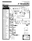
Motor Assembly/Disassembly Instructions – 3" Dynabuffer
Important: Manufacturer’s warranty is void if tool is disassembled before warranty expires.
Notice: All of the special repair tools referred to in these instructions can be ordered from Dynabrade. The 96525 Tool Repair Kit is available and the items
contained in this kit are shown on the back of this parts page. Please refer to this parts page for proper part identification.
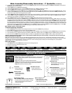
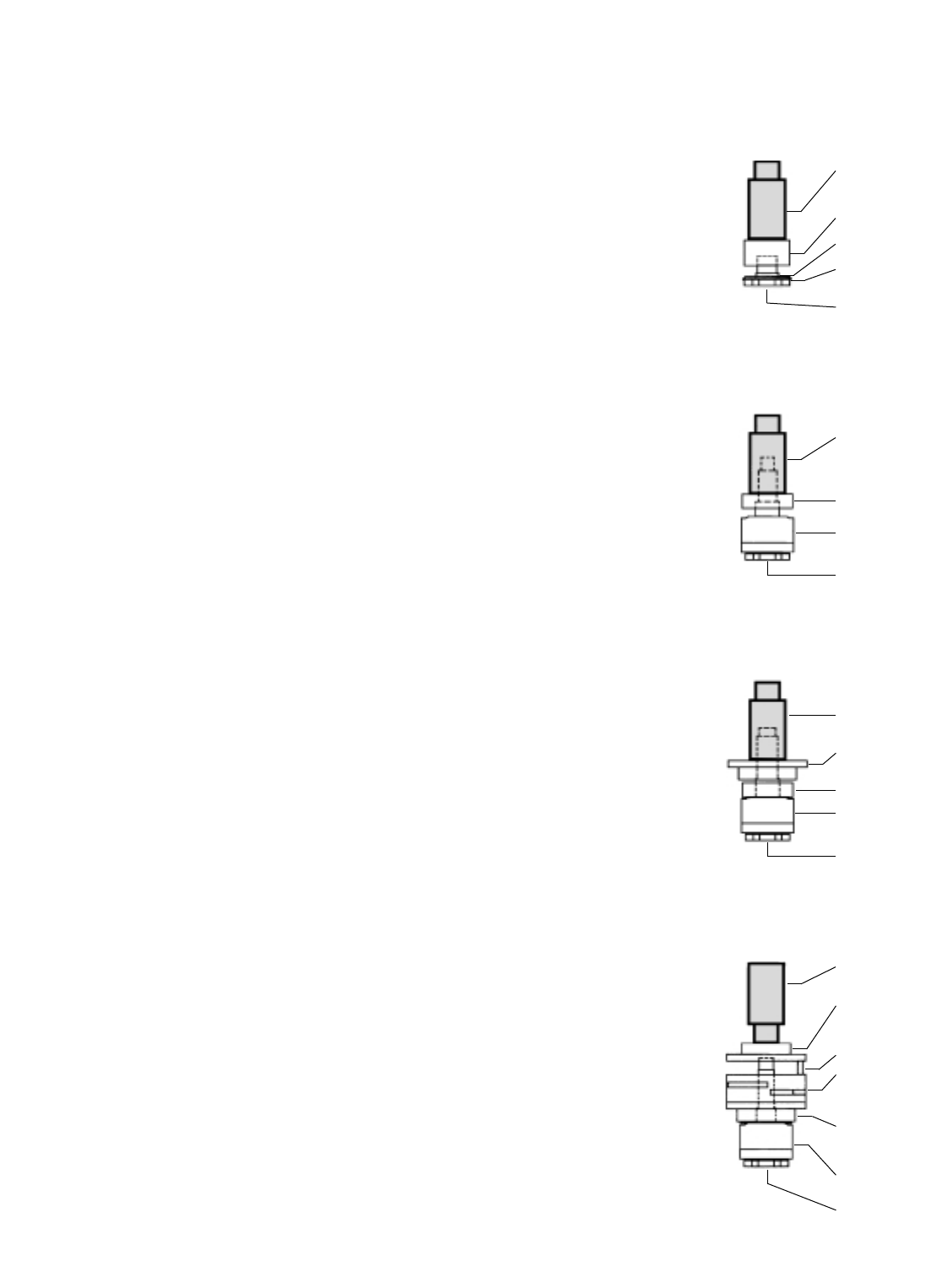
57091
Bearing Press Tool
Balancer Shaft
Assembly
Motor Shaft
Balancer
57088 Bearing
51366
Front Bearing Plate
Drawing 3
57091Bearing
Press Tool
Balancer Shaft
Assembly
Motor Shaft
Balancer
51366 Front
Bearing Plate
(with 57088 Bearing)
51367 Rear Bearing
Plate (with 01206
Bearing)
53858 Cylinder
Assembly.
(w/Rotor and Vanes)
Line-Up Pin
Drawing 4
57091
Bearing Press Tool
Balancer Shaft
Assembly
56052 Bearing
Shaft Step
Bearing Seal and
Bearing Shield
Drawing 1
Balancer Shaft
Assembly
Motor Shaft
Balancer
57088 Bearing
57091
Bearing Press Tool
Drawing 2