


7
SR Series EQ’s
OPERATION
FRONT PANEL FUNCTIONS DESCRIPTION
POWER SWITCH:Turns the power to the equalizer on or off.
EQUALIZER SLIDERS: Each one of these linear potentiometers will boost
or cut its noted frequency by +/- 12 dB. When all the sliders are in the center
detented position, the output of the equalizer is said to be flat. The numbers
marked over the top of each slider represent the center frequency that each
band will control.
INPUT LEVEL CONTROL:This control sets the signal level to the equaliz-
er. It is capable of +/- 12 dB of gain. The level is indicated on the INPUT LEVEL
BAR GRAPH. This control is used to compensate for variations in volume due
to gain changes caused by equalizing individual frequencies.
LOW CUT FILTER SWITCH:This switch electronically inserts a filter into
the signal path, which cuts the low frequencies at 12 dB per octave (-3dB @50
Hz). The LED indicator lights when the switch is depressed and the filter is in
the circuit.
IN/OUT BYPASS SWITCH: This switch inserts or removes the equalizer
channel from the signal path. An LED indicator lights when the switch is
depressed and the equalizer channel is in the circuit path. The bypass function is
FET switched to prevent switching transients when inserting the equalizer into
the circuit.
LED LEVEL INDICATOR: The LED level indicator shows the signal level to
the unit.
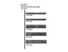
REAR PANEL FUNCTIONS
BALANCED INPUT: Accepts a standard XLR type connector [see section
on installation for wiring connections].The 1/4” phono jack may also be used for
balanced inputs when used with a TRS connector.Maximum allowable input level
is +18 dBu. Input impedance for a balanced connection is 80 kOhms.
UNBALANCED INPUT:Accepts an1/4” plug (see section on installation for
wiring connections). Connections are unbalanced. Maximum allowable input is
+18 dBu. Input impedance for the unbalanced connection is 40Ω.
BALANCED OUTPUT:Accepts a standard XLR type connector [see section
on installation for wiring connections].A 1/4" TRS jack may be used to achieve
an impedance balanced output. Maximum balanced output level is +21 dBu.
Balanced output impedance is 102 Ω.
UNBALANCED OUTPUT: Accepts a 1/4” plug (see section on installation
for wiring connections). Connections are unbalanced. Maximum unbalanced
output level is +21 dBu. Output impedance is 51 Ω unbalanced.