


AVALON RF, INC. Page 5 of 28
DX404/DX504/DX604 User’s Guide & Operating Manual
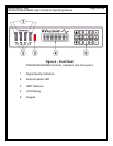
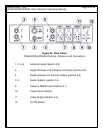
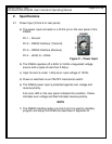
2.2 Antenna Inputs, total of 4 (Circles 1,2,5,6 on rear panel).
a) DX404: The tuning frequency range is 56MHz-802/860MHz,
AM/VSB modulated. The antenna connectors of the NTSC model
are “F” type with a 75 Ω (ohm) impedance. The PAL model has
RCA connectors.
b) DX504: The tuning frequency range is 900-928 MHz, FM
modulated. The antenna connectors are “F” type with a 75 Ω
(ohm) impedance.
c) DX604: The tuning frequency range is 2350-2500 MHz, FM
modulated. The antenna connectors are SMA type with a 50 Ω
(ohm) impedance.
2.3 Video Output (circle 11 on rear panel)
The video output through a 75 Ω (ohm) BNC connector.
a) Output is NTSC/PAL/RS170A/CCIR baseband from 20 Hz to 5.5
MHz.
b) Output amplitude is 1 Vp.p. with negative sync tips of 0.3 Vp.p.
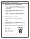
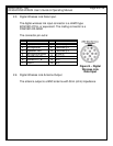
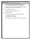
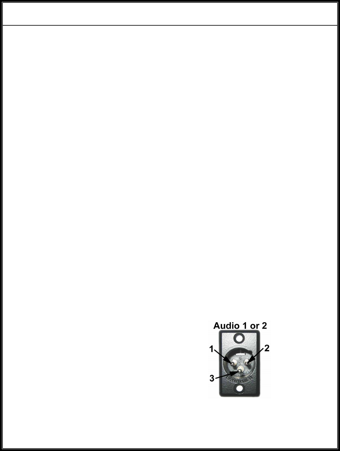
2.4 Audio Outputs (Circles 7,8 on rear panel)
Both audio outputs are XLR 3 pin connectors located on the rear
panel.
Pin 1 – Ground
Pin 2 – Audio Output (P)
Pin 3 – Audio Output (N)
Figure D – Audio Output(s)
Output is 1 V (peak to peak) into 600 Ω (ohm), balanced.