


AVALON RF, INC. Page 10 of 28
DX404/DX504/DX604 User’s Guide & Operating Manual
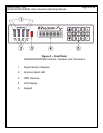
3. Operating Instructions
3.1 Human Interface.
3.1.1 Front Panel Keypad (Circle 5 on figure A)
All manual setup functions are entered via the keypad.
3.1.2 Front Panel Indicators (Circles 1,2 on figure A).
The DX604 front panel includes the following indicators:
a) Signal quality indicators for each antenna via an 8 segment LED
bar graph. The higher the illuminated LED, the better the signal
from the antenna.
b) Antenna select LED. One Green LED for each antenna. The
antenna LED indicates which of the antennas has been selected
for its best video.
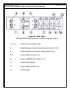
3.1.3 Front Panel Display (circle 4 on figure A)
The DX604 has a 2 line LCD display, each line capable of displaying
up to 16 alphanumeric characters.
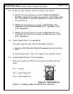
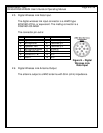
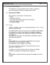
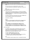
Typical DX404 display Typical DX504/DX604 display
The top line of the LCD displays the frequencies of the video carrier
and of the two audio sub-carriers (on the DX504/DX604 only) and the
channel number on the DX404. The format of the second line is
explained in Appendix A.
The display can be turned ON or OFF (see section 3.2.4).
CH #39 NTSC
01RANVL
2407.50N 6W0 6W5
01RANVL