


8
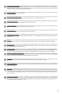
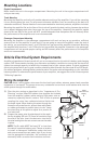
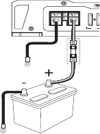
3) Trim the power cable within 18 inches (45.7mm) of the positive
battery post and splice in a in-line fuse holder. DO NOT install
the fuse at this time.
4) Strip 1/2 inch (12.7mm) from the battery end of the power cable
and crimp a large ring terminal to the cable. Connect the ring
terminal to the positive (+) battery post.
5) Prepare the ground wire for attachment to the amplier by strip-
ping 5/8” of insulation from the end of the wire, Insert the bare wire into the GND terminal
and tighten the set screw to secure the cable in place. Prepare the chassis ground by
scraping any paint from the metal surface and thoroughly clean the area of all dirt and
grease. Strip the other end of the wire and attach a ring connector. Fasten the cable to
the chassis using a non-anodized screw and a star washer.
NOTE: It is important to upgrade the ground connection between the negative (-) battery
post and the
vehicle body or chassis to achieve optimum electrical performance.
6) Prepare the REM turn-on wire for attachment to the amplier by stripping 5/8 inch
(15.9mm) of insulation from the end of the wire. Insert the bare wire into the REM terminal
and tighten the set screw to secure the wire in place. Connect the other end of the REM
wire to a switched 12 volt positive source. The switched voltage is usually taken from the
source unit’s remote amp on lead. If the source unit does not have this output available,
the recommended solution is to wire a mechanical switch in line with a 12 volt source to
activate the amplier.
7) Securely mount the amplier to the vehicle or amp rack. Be careful not to mount the
amplier on cardboard or plastic panels. Doing so may enable the screws to pull out
from the panel due to road vibration or sudden vehicle stops.
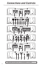
8) Connect from source signal by connecting the RCA audio cables to the input jacks at the
amplier.
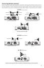
9) Connect the car speakers. Speakers should be 4 Ohms. If connecting one speaker per
channel as shown in the diagrams (except where noted on HA 750.1). Strip the speaker
wires 1/2” (12.7mm) and insert into the speaker terminal block, then tighten the set
screw to secure into place. Be sure to maintain proper speaker polarity. DO NOT chassis
ground any of the speaker leads as unstable operation or damage to the amplier and/
or speaker may result.
Power Connections
PWR
PRT
FUSE
MONO
++––
REM
GND +12V