


ENGLISH
!5
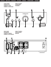
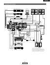
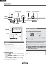
REC. (REC OUT) terminals
• These are playing and recording output terminals for
connection to tape decks.
!6
PRE OUT terminals
• Use these when adding a power amplifier, a subwoofer
with built-in power amplifier, etc.
• Connect these PRE OUT terminals to the input terminals
on the additional power amplifier, subwoofer, etc.
!7
P. DIRECT ( Power amp direct ) terminals
• Source connected to this terminal is directly fed to the
power amplifier set volume level by the component
connected to this terminal.
NOTE:
Signals are outputted from the PRE OUT terminals
even when using headphones.
No signal is outputted when selecting P. DIRECT
terminals.
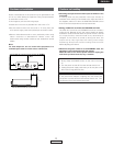
NOTE:
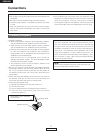
The PHONO input terminals are equipped with a short
pin-plug. Remove this plug to connect a record player.
Store the removed short pin-plug in a safe place so as
not to lose it.
o
Input indicator
The Indicator for the program source selected with the
INPUT SELECTOR control lights.
!8
SPEAKER SYSTEMS terminals
• Connect the speaker systems here.
!9
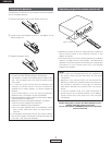
AC inlet receptacle (AC IN)
• Connect the included power supply cord here.
Do not use any other cord than the provided power supply
cord.
@0
SIGNAL GND (ground) terminal
• Connect the turntable’s ground wire here.
@1
CARTRIDGE selection switch
• This switch is set according to the type of player cartridge
to be used. Set this switch to MM (
£) or MC (¢)
according to the type of cartridge used on your turntable.
NOTE:
This terminal is used to reduce noise when a turntable,
etc., is connected.
It does not provide grounding.
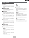
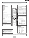
Rear panel
!4
INPUTS terminals
• These are INPUTS terminals for CD players, turntables,
AM/FM tuners, tape decks or other playback components.
!1
SOURCE DIRECT
• The controls (BASS, TREBLE and BALANCE ) can be used
when this switch is in the OFF (
£) position.
When set to the ON (
¢) position, the above controls are
by-passed and the signals are input directly to the volume
control circuit, providing high quality sound.
!2
POWER indicator
• When the POWER switch is turned ON/STANDBY(¢),
the power indicator lights.
Light green : Power is on
Light red : Power is in the standby mode
!3
Remote control sensor
• This sensor receives the infra-red light transmitted from
the wireless remote control unit.
• For remote control, point the wireless remote control unit
towards the sensor.
NOTE:
When selecting the P. DIRECT terminal, volume control
function of this unit does not work, so set volume level
by the component connecting to this terminal.
!0
P. DIRECT (Power amp direct) button
ON :
P. DIRECT terminals selected, and input indicator is turned
off.
OFF :
Selected INPUT SELECTOR knob makes program source
play.
NOTE:
When the P. DIRECT button is ON position, Input
indicator dose not light.
5
ENGLISH