


6
ENGLISH
5
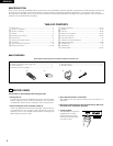
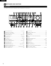
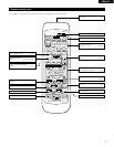
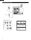
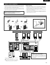
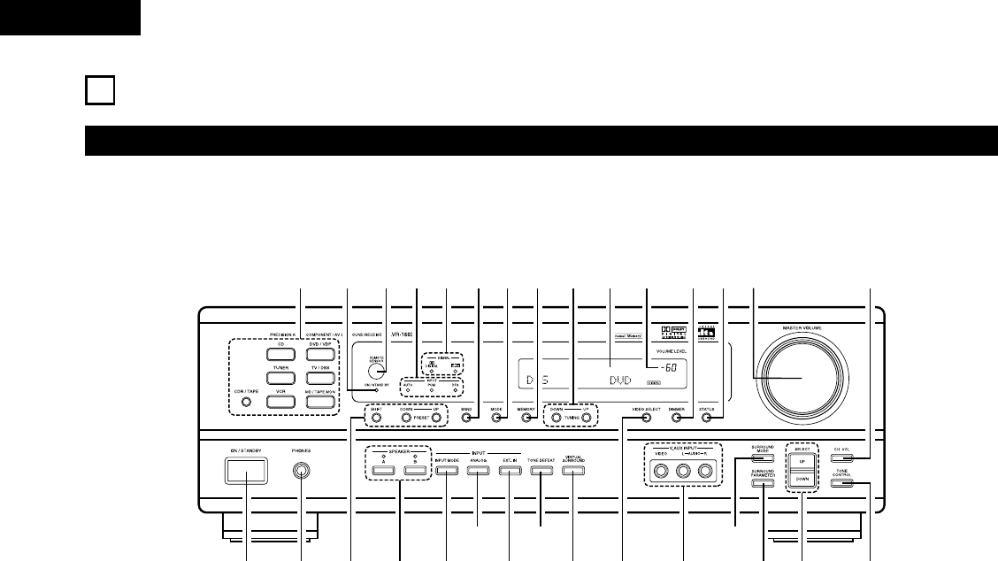
PART NAMES AND FUNCTIONS
Front Panel
• For details on the functions of these parts, refer to the pages given in parentheses ( ).
B
q w te ur
y i!2
!9@0
@1@2@3
@4
@5
@6
@7@8@9
!0 !1 !3 !4 !5o
!6!8 !7#0
q
Power operation switch ..............................................(17, 24, 39)
w
Headphones jack (PHONES)....................................................(27)
e
Preset station selector buttons ...............................................(41)
r
SPEAKER A/B buttons.................................................(24, 27, 42)
t
INPUT MODE button...................................................(25, 28, 32)
y
ANALOG button ................................................................(25, 28)
u
EXT. IN button ...................................................................(25, 28)
i
TONE DEFEAT button ............................................................(26)
o
VIRTUAL SURROUND button .....................................(34, 35, 37)
!0
VIDEO SELECT button ............................................................(27)
!1
V. AUX INPUT jacks.............................................................(4, 11)
!2
SURROUND MODE button...................................(26, 30, 32, 37)
!3
SURROUND PARAMETER button...........................................(37)
!4
SELECT UP/DOWN button .............................(26, 29, 30, 32, 37)
!5
TONE CONTROL button..........................................................(26)
!6
CH VOL button ........................................................................(29)
!7
MASTER VOLUME control......................................................(26)
!8
STATUS button ........................................................................(27)
!9
DIMMER button ......................................................................(27)
@0
Master volume indicator (VOLUME LEVEL)............................(26)
@1
Display
@2
TUNING UP/DOWN button .....................................................(40)
@3
MEMORY button...............................................................(39, 41)
@4
MODE button ..........................................................................(40)
@5
BAND button ...........................................................................(40)
@6
SIGNAL indicators....................................................................(26)
@7
INPUT mode indicators............................................................(26)
@8
Remote control sensor (REMOTE SENSOR) ..........................(15)
@9
Power operation indicator
#0
Input source selector buttons ...........................................(25, 32)