


6
R
L
R
L
R
INPUT OUTPUT
LRL
R
OUTPUT
L
R
L
L
R
L
R
L
R
L
R
DIGITAL AUDIODIGITAL AUDIO
OUTPUT
OPTICAL COAXIAL
DIGITAL AUDIODIGITAL AUDIO
B
INPUT
OPTICAL
OUTPUT
B
5
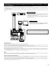
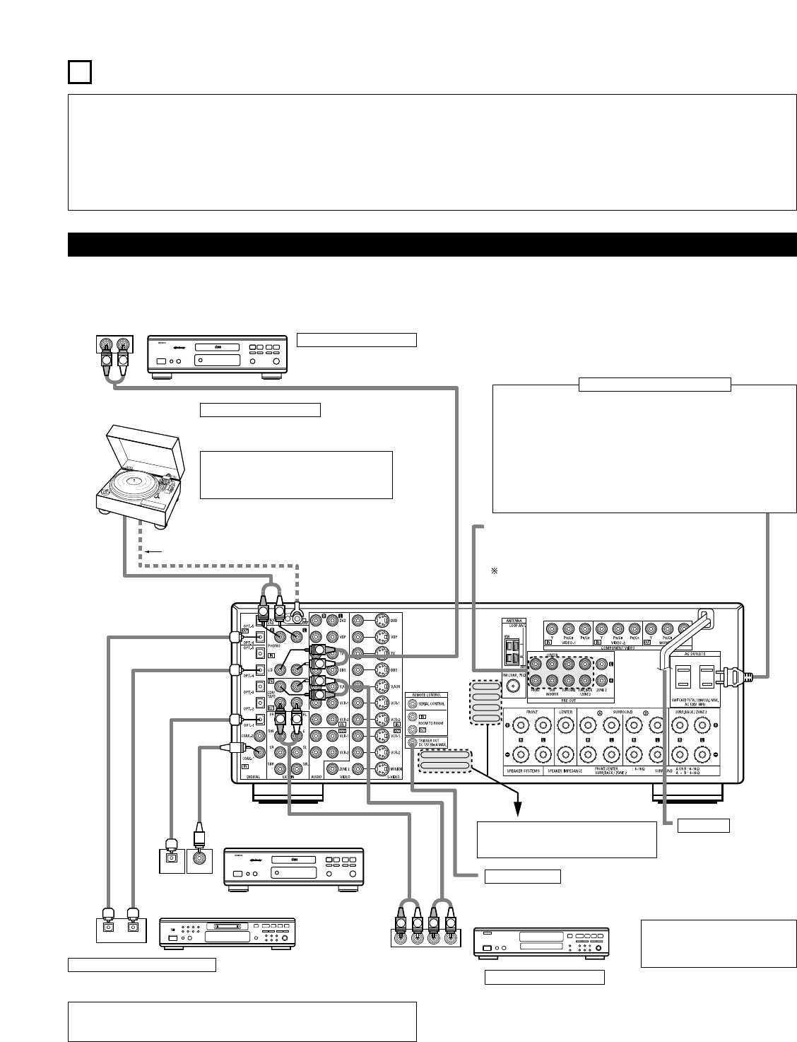
CONNECTIONS
• Do not plug in the AC cord until all connections have been
completed.
• Be sure to connect the left and right channels properly (left with
left, right with right).
• Insert the plugs securely. Incomplete connections will result in the
generation of noise.
• Use the AC OUTLETS for audio equipment only. Do not use
them for hair driers, etc.
• Note that binding pin plug cords together with AC cords or placing
them near a power transformer will result in generating hum or
other noise.
• Noise or humming may be generated if a connected audio
equipment is used independently without turning the power of this
unit on. If this happens, turn on the power of the this unit.
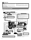
Connecting the audio components
• When making connections, also refer to the operating instructions of the other components.
The power to these outlets is turned on and off when the power is switched between on and standby from the remote control unit or power
switch.
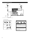
CD player
Connecting a CD player
Connect the CD player’s analog output
jacks (ANALOG OUTPUT) to this unit’s CD
jacks using pin plug cords.
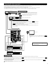
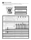
Connecting a turntable
Connect the turntable’s output cord to the AVR-
3803/1083’s PHONO jacks, the L (left) plug to the L
jack, the R (right) plug to the right jack.
NOTE:
This unit cannot be used with MC cartridges
directly. Use a separate head amplifier or step-up
transformer.
If humming or other noise is generated when the
ground wire is connected, disconnect the ground
wire.
Turntable
(MM cartridge)
Ground wire
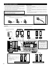
Connecting the pre-out jacks
Use these jacks if you wish to connect external power amplifier(s) to
increase the power of the front, center and surround sound channels, or
for connection to powered loudspeakers.
To use Surround back with one speaker, connect the speaker to
SURR. BACK L CH.
AC OUTLETS
• SWITCHED
(total capacity – 120 W (1 A.))
The power to these outlets is turned on and off in conjunction with the
POWER operation switch on the main unit, and when the power is switched
between on and standby from the remote control unit.
No power is supplied from these outlets when this unit’s power is at standby.
Never connect equipment whose total capacity is above 120 W (1 A.).
NOTE:
Only use the AC OUTLETS for audio equipment. Never use them for hair
driers, TVs or other electrical appliances.
Connecting the AC OUTLETS
AC CORD
AC 120 V, 60 Hz
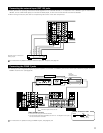
Connecting a tape deck
Connections for recording:
Connect the tape deck’s recording input jacks (LINE IN or REC) to this unit’s tape
recording (CDR/TAPE OUT) jacks using pin plug cords.
Connections for playback:
Connect the tape deck’s playback output jacks (LINE OUT or PB) to this unit’s tape
playback (CDR/TAPE IN) jacks using pin plug cords.
CD recorder or Tape deck
Route the connection cords, etc., in such a
way that they do not obstruct the ventilation
holes.
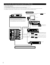
MD recorder, CD recorder or other component
equipped with digital input/output jacks
CD player or other component
equipped with digital output jacks
Connecting the DIGITAL jacks
Use these for connections to audio equipment with digital output. Refer to page 24 for
instructions on setting this terminal.
NOTES:
• Use 75 Ω/ohms cable pin cords for coaxial connections.
• Use optical cables for optical connections, removing the cap before connecting.
NOTE:
If humming noise is generated by a
tape deck, etc., move the tape deck
away.
TRIGGER OUT
Turn the DC 12V voltage on and off for the individual functions.
For details, see “Setting the Trigger Setup” on page 31.