


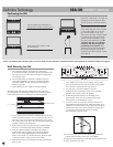
13. When the wall mounting bracket is securely screwed to the wall, line
up the speaker’s protruding Mounting Screws with the keyhole slots
on the wall mounting bracket. Let the speaker slide straight down,
allowing the screw heads to slip behind the smaller end of the keyhole
slots. Gently push the bottom front edge of the speaker toward the wall
until the speaker snaps onto the lower lip of the bracket.
Mounting the SSA to an articulating TV bracket
If you have a Plasma or LCD TV that is attached to the wall via a
swing-out articulating bracket such as those offered by Chief, Sanus
and OmniMount, the SSA speaker may be attached to the bracket
without using the SSA wall-mount plate. Simply use
1
⁄4"–20 screws to
attach the SSA speaker directly to the TV bracket. Consult the TV
bracket manufacturer’s user manual for more specific speaker
mounting instructions.
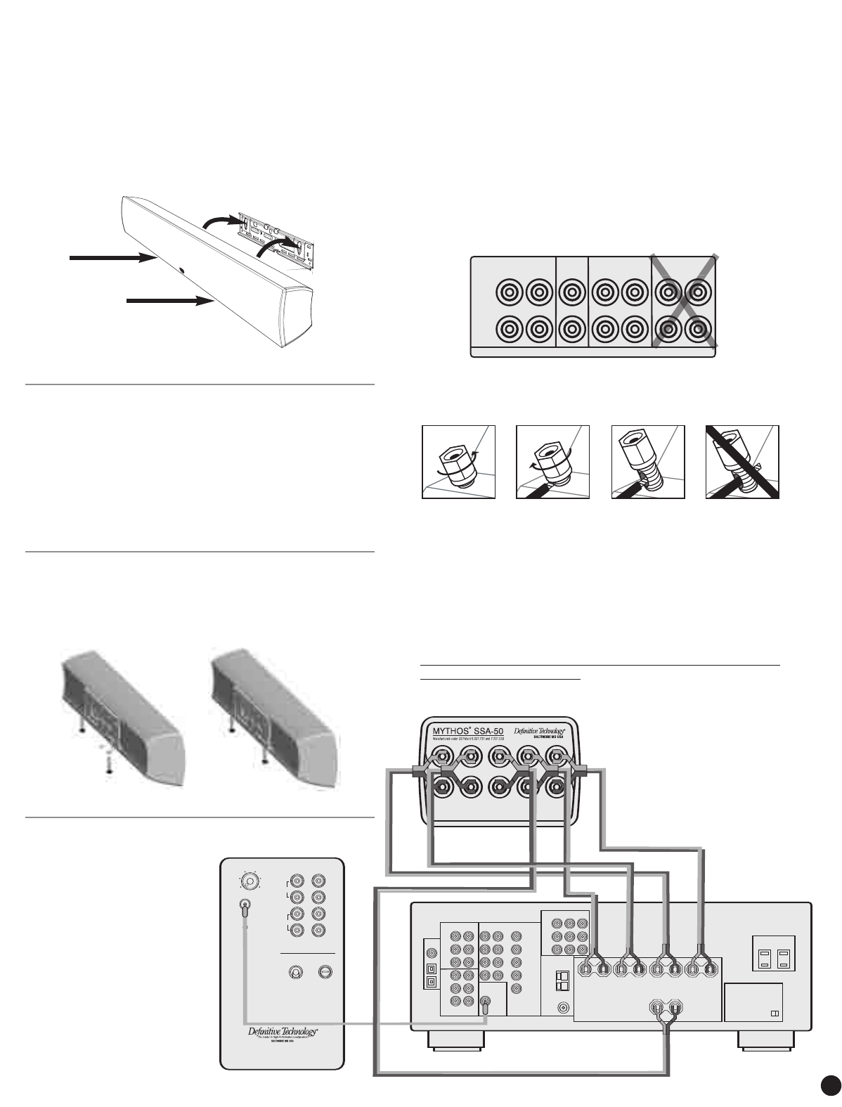
Using the Leveling Feet
If you are going to use the speaker on a TV, shelf or table, first attach
the wall-bracket to the speaker as described above. Attach the two “L”
brackets to the wall-bracket using two M4 x 10 mm screws provided.
Thread the foot screws into the two “L” brackets and adjust to the
required height.
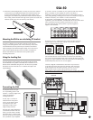
Connecting the SSA
Your Mythos SSA has one pair
of 5-way binding posts for each
channel — Left Front, Right Front,
Center, Left Surround
and Right Surround.
To start, strip
1
/
2
" (3 mm) of
insulation from each speaker
wire to expose the bare metal
wire and twist each of the
individual conductors into
single un-frayed strands.
Note that one of the terminals for
each channel is marked with red
band (+) and the other is marked
with black band (–). Make certain
that you connect the wire from the
red (+) terminal of your amplifier
or receiver to the red (+) terminal on your speaker and the wire from the
black (–) terminal of your amplifier or receiver to the black (–)
terminal on your speaker. Most speaker wire has some indicator (such as
color-coding, ribbing or writing) on one of the two conductors to help you
maintain consistency. It is essential to connect all channels
of the speaker to the amplifier in the same way (in phase). If you
experience a poor surround effect, it is likely that one or more of the chan-
nels is connected in incorrect polarity and needs to be rewired.
Pay close attention and connect positive to positive; negative to
negative on all channels.
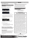
If you have a 6.1 or 7.1 channel receiver, connect the SSA’s surround
channel inputs to the “Surround” outputs of your receiver, not the
“Rear” or “Surround Back” outputs.
To connect wire to the binding post [see figure above], unscrew the knurled
nut and insert the bare wire into the hole near the base of the binding
post. Do not insert the insulated part of the wire into the hole as this will
not give you a good connection. Twist the nut back down the binding post
until it firmly meets the wire. Do not over tighten.
Connect a single RCA cable from the “SUB OUT” of your receiver
to the LFE input of the subwoofer (not included). This connecting
method bypasses the subwoofer’s internal “crossover” or low pass
filter and relies on the crossover filter built into your receiver.
NOTE: Make no other signal connections. Do not use speaker wir
e to make
the connection to the subwoofer
SSA-50
OWNER’S MANUAL
SUBWOOFER
9
5
150
40
Variable
Low Pass Crossover
120V 80Hz T 3.2A L 250V
Automatic
Power
ON/OFF
ProCinema
Subwoofer
Active Crossover
and Power Amplifier
High Level
+
+
–
–
Left Right
®
LFE
IN
In
Out
RECEIVER
AUDIO
AUDIO
MULTI INPUT
SUBWOOFER
(LFE)
OUTPUT
COMPONENT VIDEO
FRONT LEFT FRONT RIGHT SURROUND RIGHT
CENTER
SURROUND LEFT
IMPEDANCE SELECTOR
VIDEO
SSA-50
FRONT
RIGHT
CENTER
+
–
+
–
+
–
+
+
–
–
+
–
SURROUND
RIGHT
FRONT
LEFT
SURROUND
LEFT
SPEAKERS
F
RONT
RIGHT
+
–
LEFT RIGHT LEFT
CENTER
S
URROUND
RIGHT LEFT
S
URR. BACK/REAR
FT
R
RIGHT
S
3