


5
• The speaker enclosure needs to be against joists or framing material on the
2 parallel sides that are to be fastened with the screws.
• The clearance required on outside ceiling surface is 1" around the cutout to
clear the speaker bezel. On inside surface, 1
1
/
4
" of clearance is required to
clear lock arms on the sides that will not be fastened to the joists or framing
material.
• Also note that the installation of the RCS III may require some modifica-
tion of the joist structure in your ceiling. This should only be done by a
competent professional who will configure the studs to maintain their
structural integrity and make sure that everything is in compliance with all
local and state building code requirements.
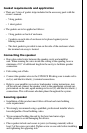
• Speaker wire must be run inside your ceiling as part of the installation
process of in-wall loudspeakers. Plan the connection before you start your
loudspeaker installation.
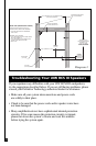
Installation Procedure Overview (continued)
Step-by-Step Installation
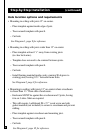
Mounting options overview
• Installation of this product must follow all local and state building codes.
• We strongly recommend using a qualified, professional installer who is
knowledgeable of local building codes.
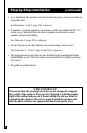
Required cutout and cavity size
• Template cutout size: 10
3
/
8
"W x 10
3
/
8
"L.
• Minimum size of installation cavity (inside ceiling and between joists)
is as follows:
– Depth: 5
7
/
8
"
–10
1
/
2
" between joists on the sides the wood screws are to be installed in.
– 12
3
/
4
" between joists on sides the lock arms are to be used
(1
1
/
4
" of space required on each side to clear lock arms).
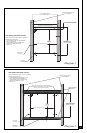
See Diagram 1, page 9 for r
efer
ence.