4
Front Panel
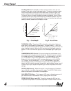
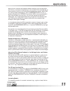
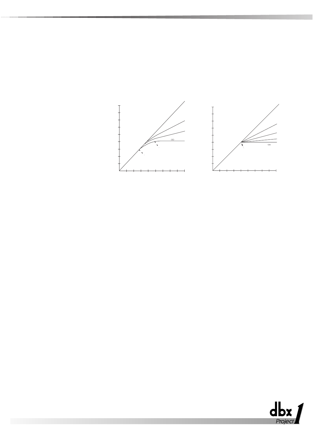
OverEasy® Switch: OverEasy® provides a smooth transition from the com-
pressor’s linear region to the compressed region. This smooth transition greatly
reduces compression artifacts and allows faster attack times and higher com-
pression ratios while still maintaining the natural characteristics of the signal.
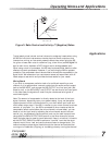
The switch lights to indicate OverEasy® processing is enabled. Figure 1 below
illustrates the the input/output relationships for OverEasy® operation. Figure 2
illustrates the same for hard knee operation. When conventional hard knee pro-
cessing is desired, disable the OverEasy® function
.
Fig. 1 -OverEasy® Fig. 2 - Hard Knee
THRESHOLD LEDs: These three LEDs indicate the relationship of the input
signal level to the threshold of compression. The green “below” (-) LED is on
when the signal is below threshold and the red “above” (+) LED is on when the
signal is above threshold. When the 262 is switched to OverEasy® mode, the
amber “O” LED is on when the signal is in the OverEasy® region (See Figure
1).
COMPRESSION RATIO Control: This control selects the ratio between input
and output levels for signals above the threshold. Rotate this control clockwise
to increase the amount of compression from 1:1 (no compression) up to infini-
ty:1 (no increase in output level, regardless of input level increases above
threshold); further clockwise rotation increases compression into the INFINI-
TY+™ region, up to a maximum of -1:1 (i.e., a 1dB increase in input level
above threshold causes a 1dB decrease in output level). In the INFINITY+™
region, the 262 inverts the program dynamics for special effects. Figures 1 and 2
illustrate input/output slopes corresponding to various compressor/limiter ratio
settings.
OUTPUT GAIN Control: Adjust this control to vary the amount of fixed gain
(up to ±20 dB) in the 262’s output amplifier stage. The OUTPUT GAIN control
does not interact with the threshold of compression.
GAIN REDUCTION Meter: This 8-segment LED meter indicates the amount of
gain reduction due to compression/limiting, ranging from 0 to 30 dB.
STEREO COUPLE Switch and LED: This switch changes the 262 from two
independent compressors into a stereo compressor. In Stereo mode, Channel 1
-15
-10
-5
0
+5
+15
+20
+10
INPUT LEVEL (dB)
OUTPUT LEVEL (dB)
-15
-10
-5
0
+5 +15
+20
+10
1:1 Unity
2:1
4:1
:1
20:1
RED
Above Threshold
GREEN
Below Threshold
Rotation Point Threshold
1:1
2:1
4:1
:1
-
15
-
10
-
5
0
+5
+15
+20
+10
INPUT LEVEL (dB)
OUTPUT LEVEL (dB)
-
15
-
10
-
5
0
+5
+15
+20
+10
RED
Below Threshold
Above Threshold
OverEasy Range
G
R
E
E
N
A
M
B
E
R


