


(3)
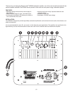
INPUT CONNECTIONS
1.) Left/Right inputs
RCA style jacks that will accept standard line level inputs
from a pre-amp level source. They will accept a stereo signal
and internally combine it into mono. Both left and right input
jacks must be connected to the source in order to drive the
amplifier to full output. The use of a “Y” cord is suggested if a
mono source is all that is available.
2.) LFE direct input
RCA jack that will accept a signal from the mono LFE (Low
Frequency Effects) output on a pre-amp or receiver that is
equipped with a dedicated sub bass output. This input by-
passes the amplifier’s own internal low pass filter circuitry,
relying instead on the processed output provided by the source
equipment. This would be the recommended connection for
most home theater surround sound receivers and pre-amps.
We would also suggest the use of the LFE input when an
external line level electronic crossover or frequency dividing
network is used.
3.) Power input
This unit features an IEC grounding type power input connec-
tor. The IEC inlet connector also features an integrated fuse
holder that contains the AC line fuse. For 230V input, remove
the fuse holder, rotate 180 degrees, and re-install. In most
230V applications a separate power cord will be required
and is not included.
CONTROLS/INDICATORS
4.) Low Pass, Gain
Will match the amplifier’s input sensitivity to the output of the
pre-amp source. If the source output has a variable control,
we recommend that the user spend a moment or two deter-
mining the best balance between the two controls. When a
balance is found between low noise, linear level control, and
sufficient level to drive the amp to the required output, the
gain knob can be considered to be the “volume control” for
the subwoofer system.
5.) Low Pass, Frequency
This control is used to establish the highest frequency that
the subwoofer will reproduce and has a range between 30
and 200 Hz. If your main speakers have good bass capabil-
ity, you could set the control to a fairly low value at 40, 60,
or even 100 Hz. If the main speakers are smaller or do not
have much bass output, set the control higher. Experiment
with the amount of “overlap” that you will experience when all
speakers are playing in the same range. This can be helpful
when integrating the subwoofer with the rest of the system
and with the room.
6.) Power Switch
This switch manually turns the unit on and off. When switched
to the on position, the unit will first turn on and be fully opera-
tional. After a period of 10-15 minutes without a signal the unit
will go into “stand by” mode.
7.) Power LED
When the power switch is moved to the “on” position, the
LED will illuminate in green, and the amp will be in “stand
by” mode. If a low level signal of about 3 millivolts or greater
is applied to the input, the light will change color to yellow to
indicate that the amplifier is fully operational and receiving
typical music program. As input signal increases to the onset
of clipping the LED will turn red, which indicates that the clip
limiting circuitry is activated. If an input signal is not detected
for 10 to 15 minutes, the amp will go back to “stand by” mode
and the LED will change back to green.
8.) Phase
This two-position (NOR = 0° phase and REV = 180° phase)
switch helps to compensate for differences in the acoustical
and electrical characteristics between the subwoofer and the
main system speakers. The relative locations of speakers in
the system can cause significant disturbances in speaker
interaction due to time delay issues, or the destructive phase
interferences that can occur at certain frequencies. The use
of this switch in conjunction with altering the location of the
subwoofer can have a dramatic effect on system integration.
The “NOR” setting would be considered the normal or default
setting, but be sure to experiment during system set-up.
PARAMETRIC EQUALIZER
The SPA500 features a fully parametric equalizer to help you
to achieve the best possible subwoofer performance. Profes-
sional sound engineers have for many years considered the
parametric EQ to be one of the most accurate, versatile, and
high fidelity tools for audio enhancement. A greater degree of
control can be achieved when using the EQ’s unique ability
to vary the frequency to be affected, the amount of boost or
cut, and the width or narrowness at the selected frequency.
9.) EQ-Frequency
Establishes the specific frequency at which EQ boost or cut
may be applied between 18 Hz and 80 Hz.
10.) EQ-Bandwidth
Determines how narrow or wide the EQ curve will be within a
range of 0.1 to 1.0. If for example a frequency of 60 Hz were
selected along with a Q of 0.1, the frequencies to either side
of 60 Hz would be less affected. This is a narrow bandwidth
that could be useful for “surgically” removing an offending peak
without disturbing adjacent frequencies. At the other extreme,
a Q of 1 would result in a much broader effect which could
be used for smooth overall bass boost or cut, to balance the
overall tone character of the sub.
11.) EQ-Level
Permits the application of up to 6 dB of boost or 14.5 dB of cut
at the selected frequency and bandwidth. Setting the control
at the 0 position effectively removes the EQ from the circuit
path. It is good to remember that high levels of boost reduce
amplifier headroom; it is the same as turning up the low pass
gain control but only at the selected EQ frequencies. It would
be helpful to reduce or increase the low pass gain control to
balance the amount of cut or boost applied by the EQ.
12.) Output Lead for Subwoofer Driver:
This rear mounted output lead connects the amplifier to the
subwoofer driver. The output lead is roughly 20" long and
is color coded. The red wire uses an insulated .250" quick
disconnect and the black wire uses an insulated .205" quick
disconnect. These connectors can be easily removed if your
driver requires another size or type of connector. Be sure to
observe proper polarity when connecting the amplifier to your
subwoofer driver (red = positive, black = negative).