


(3)
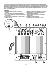
INPUT/OUTPUT CONNECTIONS
1.) Low-Level Inputs (Left/Right)
RCAstylejacksthatwillacceptstandardlinelevelinputsfrom
apre-amplevelsource.Theywillacceptastereosignaland
internallycombineitintomono.Bothleftandrightinputjacks
mustbeconnectedtothesourceinordertodrivetheamplier
tofulloutput.Note: IfusingaLFEoutputfromapreampor
receiverconnectittotheLeft(mono)input.
2.) Low-Level Outputs (Left/Right)
Thisoutputallowsthelowlevelinputsignaltobedaisychained
tootherampliers.Thelowlevelinputissimplypassedthrough
withnoalteration(EQ)totheoriginalsignal.
3.) High-Level Inputs
Speakerlevelinputsusingbindingposttypejackstopermit
connectionwithbananatypeplugsorspadeterminals.Allows
theusertoconnectthespeakerleveloutputofafullrange
ampliertotheinputofthesubwooferampusingstandard
speakerwire.Amonosignalisderivedfromthestereo,which
thenfeedsthesubwooferampliercrossoverinput.
4.) High-Level Outputs
Speakerleveloutputsusingbindingposttypejackstopermit
connectionwithbananatypeplugsorbarewire.Usedtocon-
nectfromthesubwooferamptopasssignalfromthefullrange
ampontothemainL/Rspeakers.Signalisonlypresenton
thisoutputifthehighlevelinputisalsoused.Thesignalto
theL/Rspeakerswillbeshapedbyaninternal6dB/octave
125Hzhighpasslter.
5.) Power input
ThisunitfeaturesanIECtypepowerjack.Thisallowsthe
usertochangethepowercorddependingonthecountry
andvoltageused.TheIECjackalsohousesanintegrated
fuseholderthatcontainstheAClinefuse.Theunitissetat
thefactoryfor115Voperation.Itissuppliedwitha5A,250V
fuseandUSAtypepowercord.Inmost230Vapplicationsa
separatepowercordand2.5A,250Vfusewillberequired
andarenotincluded.
CONTROLS/INDICATORS
6.) Gain
Thiscontrolwillmatchtheamplier’sinputsensitivitytothe
outputofthepre-ampsource.Ifthesourceoutputhasavari-
ablecontrol,werecommendthattheuserspendamomentor
twodeterminingthebestbalancebetweenthetwocontrols.
Whenabalanceisfoundbetweenlownoise,linearlevel
control,andsufcientleveltodrivetheamptotherequired
output,thegainknobcanbeconsideredtobethe“volume
control”forthesubwoofersystem.
7.) Frequency
Thiscontrolisusedtoestablishthehighestfrequencythat
thesubwooferwillreproduceandhasarangebetween40to
180Hzwithaslopeof24dBperoctave.Ifyouareusingthe
systemformusicandyourmainspeakershavegoodbass
capability,youcouldsetthecontroltoafairlylowvalueat40,
60,oreven100Hz.Ifthemainspeakersaresmallerordo
nothavemuchbassoutput,setthecontrolhigher.Experiment
withtheamountof“overlap”thatyouwillexperiencewhenall
speakersareplayinginthesamerange.Thiscanbehelpful
whenintegratingthesubwooferwiththerestofthesystemand
withtheroom.Note: Whenusingtheampwitha LFE(Low
FrequencyEffects)outputonapre-amporhometheatrere-
ceivertheinternallowpassltercircuitryshouldbebypassed
byturningthefrequencycontroltomaximum(180Hz).The
hometheaterreceivershouldbeusedtocontrolthelowpass
crossoverfrequency.
8.) Power LED
Whenthepowerswitchismovedtothe“on”position,theLED
willilluminategreen,andtheampwillbein“On”mode.When
setinthe“Auto”positiontheunitwillbeinthestandbymode.In
thisposition,ifalowlevelsignalofabout10millivoltsorgreater
isappliedtotheinput,thelightwillchangegreentoindicate
thattheamplierisfullyoperationalandreceivingtypicalmusic
program.Ifaninputsignalisnotdetectedfor10to15minutes,
theampwillgobackto“standby”modeandtheLEDwillturn
off.Iftheprotectioncircuitdetectsashortcircuitorthermal
overloadtheunitwillshutdownandtheLEDwillturnred.
9.) Power Switch
On,OffandAutomode.Whenthe“Auto”positionisselected,
theampisin“standby”modeuntilaninputsignalofabout
10millivoltsorgreaterisdetected.Theampwillgobackto
standbymode10-15minutesaftertheinputsignalstops.
10.) Phase
Thistwo-position(NOR=0°phaseandREV=180°phase)
switchhelpstocompensatefordifferencesintheacoustical
andelectricalcharacteristicsbetweenthesubwooferandthe
mainsystemspeakers.Therelativelocationsofspeakersin
thesystemcancausesignicantdisturbancesinspeaker
interactionduetotimedelayissues,orthedestructivephase
interferencesthatcanoccuratcertainfrequencies.Theuse
ofthisswitchinconjunctionwithalteringthelocationofthe
subwoofercanhaveadramaticeffectonsystemintegration.
The“NOR”settingwouldbeconsideredthenormalordefault
setting,butbesuretoexperimentduringsystemset-up.
11.) Voltage Selector Switch
Thisswitchallowstheusertoselect115Vor230Voperation.
Theunitissetatthefactoryfor115Voperationandcontains
a5A,250Vfuse.Whenoperatingat230Vbesuretochange
thefusetoa2.5A,250Vfuse.
12.) Output Lead for Subwoofer Driver:
Thisrearmountedoutputleadconnectstheampliertothe
subwooferdriver.Theoutputleadisroughly20"longand
iscolorcoded.Theredwireusesaninsulated.250"quick
disconnectandtheblackwireusesaninsulated.205"quick
disconnect.Theseconnectorscanbeeasilyremovedifyour
driverrequiresanothersizeortypeofconnector.Besureto
observeproperpolaritywhenconnectingtheampliertoyour
subwooferdriver(red=positive,black=negative).
13.) Bass Boost:
Selectsabassboostlterwith+6dB@35Hz.Allowstheuser
toaddboosttothelowendresponse.Removeplugtoaccess
switchNOTE: DO NOT attempt to change bass boost set-
ting when ampliifier is turned on.